
Specifications


42” HD Gas Plasma Display Rosen Aviation Displays, LLC
42
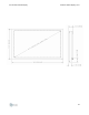
OUTLINE DRAWINGS
Scope
The following drawing established the package outline of the 42” HD Gas Plasma Display.
General
Interpret this drawing in accordance with MIL-STD-100.
All dimensions are in inches followed by the equivalent in millimeters placed in brackets
[mm]. Do not scale this drawing.
Configuration
• Power Input: 115V AC via J1
• Data Inputs:
Optional NTSC Antenna Input via J2
S-Video Input via J5
Component Video via J6, J7, J8
Digital Video + Analog RGB Input via J9
Serial Data via J10
S-Video + Component Analog Video, or 3X Composite Video via J4, using
Video Bundle Cable
• Outputs:
Optional DC Power Output via J11
Optional IR Remote Output via J1
• Standard Case Color: Black
Mounting Requirements
Mount Unit with # 1/4 x 20 with Threaded Holes on Rear of Unit.
Allow at Least One Inch Clearance Above and Below the Unit for Ventilation.
SYM TYPE FUNCTION
J1 IEC-320 AC Power Input
J2 F-Connector Unused
J3 Stereo Phone Jack IR Remote Out (optional)
J4 8-Pin DIN S-Video (2) / CAV (2). CVS (1) (2) (3)
J5 4-Pin DIN S-Video
J6 BNC Pb
J7 BNC Pr
J8 BNC Y
J9 DVI DVI/RGB
J10 RJ-45 RS-232
J11 2mm Power Jack 12V DC Out (optional)