
Technical data

Analog Integrated Circuit Device Data
Freescale Semiconductor 25
34825
FUNCTIONAL DEVICE OPERATION
OPERATION AFTER IDENTIFICATION
USB HOST (PC OR HUB)
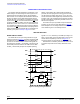
When the attached accessory is a USB host or hub, the ID
pin is floating. The power MOSFET is turned on to allow the
charger to charge the battery. The
ISET outputs default high
impedance to limit the charging current to a lower level. The
host IC can turn on the D+ and D- switches and then pull the
D+ signal to high to start the USB attaching sequence.
USB CHARGER OR DEDICATED CHARGER
When the attached accessory is a USB Charger or a
Dedicated Charger, the 34825 turns on the power MOSFET
to allow the charger to start. The host IC can set the
ISET
outputs low impedance to allow a higher charge current.
5-WIRE CARKIT CHARGER (TYPE 1 OR TYPE 2)
A 5-wire carkit charger is a charger specified in the CEA-
936-A USB Carkit Specification. The 5-wire carkit charger
outputs 5.0
V to the VBUS pin, has the D+ and D- pins
shorted internally, and has an ID resistor. The ID resistor has
a value of either 200
k or 440 k to distinguish the current
capability of the charger. Refer to the CEA-936-A USB Carkit
Specification for more information.
When the attached accessory is a 5-wire carkit charger,
the 34825 turns on the power MOSFET to allow the Li-ion
battery charging function to start. The host can set the
ISET
outputting high-impedance or low impedance to choose the
charge current.
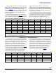
RESERVED ACCESSORY
The users can assign the reserved ID resistor values listed
in Table 22 to their user specific accessories. When a user
specific accessory is attached, the identification flow will
identify the ID resistance and as well as the power supply
type in case of a powered accessory. The ADC Result
register and the Status register contain the information of the
R
ID
value and the power supply type. The baseband can read
these registers to distinguish the type of the accessory for
further actions.
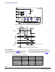
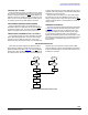
DETACHING DETECTION
When either the VBUS voltage drops below the VBUS
power detection threshold or the ID resistor is removed, a
detaching detection flow starts.
Figure 18 shows the detailed
detection flow. When the DETACH bit is set, the INT outputs
low voltage to inform the host IC. At the end of the detaching
detection flow, the ACTIVE bit is cleared and the 34825
enters the Standby mode. A new identification flow will start
if either the VBUS voltage is above its POR threshold or the
ID resistor is connected.
Figure 18. The Detachment Detection Flow
VBUS
Removed
Clear
VBUS_DET bit
Clear
ATTACH bit
Set
ID_FLOAT bit
ID Float
No
Yes
Set
DETACH bit
Clear
ACTIVE bit
VBUS=5V
RID
Connected
Yes
No