
Technical data

Analog Integrated Circuit Device Data
Freescale Semiconductor 21
34825
FUNCTIONAL DEVICE OPERATION
ACCESSORY IDENTIFICATION
The ADC results are broken into two groups. The values
between ‘00001’ to ‘01101’ are assigned to 13 remote-control
keys for the two accessories that support remote controllers,
as listed in
Table 22. The rest of the ADC results are
assigned to various accessories. If the ADC result is one of
the remote control key values in the identification flow, it is
possible that the remote control key is stuck when the
accessory is attached.
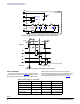
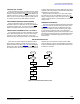
A special Stuck Key Identification flow is designed to
resolve such an issue. As shown in the Figure 14, if the stuck
key is recognized but is released within 1.5s, the identification
flow will return to re-detect the ID line; Otherwise, the
ATTACH bit will be set and the ADC Result register has the
key result. After the key is released, the 34825 will detect the
ID resistance value again. If the accessory is still connected,
the ATTACH bit is set again and the ADC result has the ID
resistor value of the accessory.
When the ADC result is 00000, the resistance between the
ID pin and the ground is less than 1.90
k. The ID_GND bit
in the Status register indicates whether the ID pin is shorted
to ground or not. If the ID pin is shorted to ground with less
than 30
of resistance, the ID_GND pin is set to “1”.
POWER SUPPLY TYPE IDENTIFICATION
The 34825 supports various standard power supplies for
charging the battery. The power supplies supported include
those that are user defined, and the ones defined in the
Battery Charging Specification, Revision 1.0, from the USB
Implementer’s Forum and the CEA-936-A USB Carkit
Specification, from the Consumer Electronics Association.
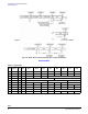
The five types of power supplies specified in the afore
mentioned two specification documents are listed in
Table 8.
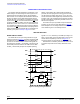
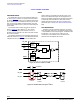
The Power Supply Type Identification (PSTI) function is
offered to assist the identification of the power supply type.
The PSTI state machine checks the connection status
between the DP and the DM pins. The state machine starts
when the VBUS pin voltage rises above the VBUS detection
threshold, which is indicated with an VBUS_DET bit in the
status register. The state machine will find out if the DP and
DM pins are shorted, indicated with the DP/DM_SHORT bit,
or the connection has the characteristics of a USB charger,
indicated with the USB_CHG bit. Together with the ID
detection result, the power supply type can be determined.
The conditions for reaching the conclusion of the five
supported power supplies are listed in
Table 8.
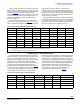
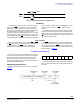
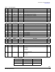
Table 7. ADC Output vs. Resistor Values (Unit: k)
ADC Result R
ID
(k) ADC Result R
ID
(k) ADC Result R
ID
(k) ADC Result R
ID
(k)
00000
(1)
01000 10.03 10000 40.2 11000 255
00001
2.00 01001 12.03 10001 49.9 11001 301
00010
2.604 01010 14.46 10010 64.9 11010 365
00011
3.208 01011 17.26 10011 80.6 11011 442
00100
4.014 01100 20.5 10100 102 11100 523
00101
4.820 01101 24.07 10101 121 11101 619
00110
6.03 01110 28.7 10110 150 11110 1000
00111
8.03 01111 34.0 10111 200 11111
(2)
Notes
1. If the ID resistance is below 1.90 k (nominal value), the ADC result is set to 00000.
2. If the ID line is floating, the ADC result is set to 11111
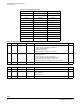
Table 8. Power Supply Type vs. Detection Result
Item # VBUS_DET DP/DM_SHORT USB_CHG ID_FLOAT ADC Result Accessory Type
1
1 0 0 1 11111 Standard USB Port
2
1 0 1 1 11111 USB Charger
3
1 1 0 1 11111 Dedicated Charger
4
1 1 0 0 10111 Carkit Charger Type 1
5
1 1 0 0 11011 Carkit Charger Type 2