
Technical data

Analog Integrated Circuit Device Data
20 Freescale Semiconductor
34825
FUNCTIONAL DEVICE OPERATION
ACCESSORY IDENTIFICATION
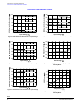
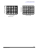
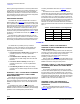
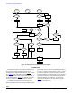
Figure 14. Detailed Accessory Identification Flow Diagram
ID DETECTION
The ID detection relies on the resistance between the ID
pin and the ground (R
ID
) inside the accessory for the
accessory detection and recognition. The nominal ID
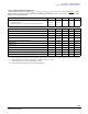
resistance that the 34825 supports is listed in
Table 7 as well
as in Table 22. The 34825 offers a 5-bit ADC for the
resistance recognition and the corresponding ADC results vs.
the R
ID
are also listed in Table 7. The resistors are required
to have 1% or better accuracy for the ADC to recognize
successfully.
A comparator monitors the ID pin for attachment and
detachment detection. When no accessory is attached, the ID
pin is floating. An ID_FLOAT bit in the Status register stays in
the value of 1. When a resistor less than or equal to 1.0
M
is connected between the ID line and the ground, the
ID_FLOAT bit changes to 0. When the resistor is removed,
ID_FLOAT bit returns to 1. A falling-edge of the ID_FLOAT bit
represents the attachment of the accessory and the ADC is
enabled to measure the ID resistance. The ADC Result
register has the identification result of the R
ID
, as given in
Table 7. A rising edge of the ID_FLOAT bit represents the
detachment of the accessory.
No
Yes
DP->DM
SHORT?
No
Yes
Set
USB_CHG bit
ID_FLOAT
=1?
VBUS
Applied?
Set DP/DM
_SHORT bit
Set
VBUS_DET bit
No
Yes
No
Key Released
within 1.5s?
Yes
ID Float?
No
Set
DETACH bit
Key
Released?
No
Yes
Set
ADC RESULT
Yes
No
ADC =
Key Value?
ADC =
1000x?
ADC =
0111x?
No
YesYes
No
No
Set
ATTACH bit
Set
ATTACH bit
Set
ID_FLOAT bit
VBUS=0V ACTIVE = 0
Yes
No
ID Float?
Clear
ID_FLOAT bit
ID Float
Yes
Delay
TD time
Yes
Set
ACTIVE bit
ADC =
00000?
ID shorted
to GND?
VBUS_DET
=1?
Set
ID_GND bit
Yes
Yes
No
No
DM->DP
SHORT?
Yes
No
Turn on
USB switches
Turn on
UART
switches