
Technical data

Analog Integrated Circuit Device Data
Freescale Semiconductor 19
34825
FUNCTIONAL DEVICE OPERATION
ACCESSORY IDENTIFICATION
ACCESSORY IDENTIFICATION
Accessories are categorized into two groups. Powered
accessories are accessories that supply power to the VBUS
pin while non-powered accessories do not. When the
accessory is a powered one, the VBUS detection mechanism
will check the connection between the D+ and the D- pins as
part of the power supply type identification (PSTI). A powered
accessory may or may not have an ID resistor. A non-
powered accessory must have an ID resistor for the
identification purpose.
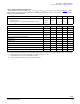
Accessories that have an ID resistor are grouped into
three types, as listed in Table 22.
1. Test Accessories. Such accessories include two USB
test cables that are powered accessories, and two
UART test cables that are non-powered accessories. A
test accessory has an ID resistor and four ID resistor
values are reserved for them (see
Table 22 for the ID
resistor assignment). The USB or the UART switches
in the IC will be turned on automatically when a test
accessory is attached.
2. Accessories with a remote controller. Two accessories
are offered to support remote control (RC) keys. The ID
resistor values are 619
k and 1.0 M respectively, as
given in Table 22. Such accessories are non-powered
accessories. The 34825 monitors the ID pin
continuously for key pressing when such an accessory
is connected. 13 ID resistors are assigned to the
remote control keys, as listed in
Table 22.
3. Other accessories. The remaining ID resistor values
are reserved for users to assign to their own
accessories.
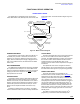
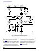
The identification flow chart is shown in Figure 14. In the
Standby mode, the 34825 monitors both the ID pin and the
VBUS pin simultaneously. If an accessory is detected, the
identification state machine will find out in parallel the ID
resistor value and the type of the power supply (if a powered
accessory is attached). When the 34825 is in the Active mode
with the ACTIVE bit = 1, the host IC can force the ACTIVE bit
to 0 via the I
2
C bus to initiate the identification state machine.
The details on the identification flow for the VBUS-
detection mechanism and the ID detection mechanism are
described as following.