
Technical data

Analog Integrated Circuit Device Data
Freescale Semiconductor 17
34825
FUNCTIONAL DEVICE OPERATION
OPERATIONAL MODES
FUNCTIONAL DEVICE OPERATION
OPERATIONAL MODES
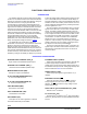
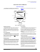
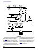
The 34825 has five operational modes: Power Down
mode, VBUS Power mode, Standby mode, Active mode, and
Power Save mode. The mode transition diagram is given in
Figure 13.
Figure 13. Mode Transition Diagram
POWER DOWN MODE
The Power Down mode is when neither the VDD pin nor
the VBUS pin is powered. In this mode, the IC does not
respond to any accessory attachment except for a power
supply. When an external power supply is plugged into the
mini or micro-USB connector, the 34825 enters the VBUS
Power mode.
VBUS POWER MODE
The 34825 enters the VBUS Power mode when the VBUS
pin is powered but the VDD pin is not. In the VBUS Power
mode, the internal power MOSFET is turned on to power the
charging function in the cell phone. The
ISET pin outputs
high-impedance in this mode.
STANDBY MODE
The Standby mode is when the VDD voltage is higher than
the POR (Power-On-Reset) threshold and no accessory is
attached. In this mode, only the ID detection circuit, the I
2
C
interface, and the internal registers are powered in order to
minimize the quiescent current from the VDD pin. The ID
detection circuit samples the status of the ID line every
50
ms.
If detecting an attachment of an accessory, the 34825
moves to the Active mode for further accessory identification.
ACTIVE MODE
The Active mode starts when an accessory is plugged into
the mini or micro-USB connector while the VDD pin is
powered. The 34825 identifies the accessory and interrupts
the host IC for further actions. Different functions will be
enabled according to the identification result, so the
quiescent current in Active mode is dependent on the type of
accessories.
The operational mode can be changed from Active to
Standby either by an accessory detachment or by resetting
the ACTIVE bit to 0 through an I
2
C programming operation.
POWER SAVE MODE
The Power Save mode can be enabled only for
accessories with a remote controller (refer to Table 22). The
34825 enters into the Power Save mode to minimize the
operating current while such an accessory is attached, but
not in operation. For example, if the cell phone is not in an
audio playback mode when a headset is attached, the host IC
can force the 34825 to the Power Save mode via the I
2
C
programming. The 34825 can also automatically enter into
the Power Save mode when no activity is detected on the
SPK_R or SPK_L pins in 10 seconds. The VDD current in the
Power Save mode is slightly higher than the current in the
Standby mode.
The 34825 can exit the Power Save mode by an I
2
C
programming or will exit the mode automatically when
V
DD
> V
VDDPOR
Active
V
DD
< V
VDDPOR
ID det or VBUS det
V
DD
< V
VDDPOR
Standby
I
2
C resets ACTIVE bit or
detachment of accessory
Power
Down
VBUS
Power
V
DD
> V
VDDPOR
VBUS power up
VBUS power down
Power
Save
I
2
C or detection
of no activity
I
2
C or detection
of the activity
Detachment
of accessory