
Owner`s manual

80
Type in Section Title
U
S
I
N
G
C
C
P
E
D
I
T
O
R
T
O
P
R
O
G
R
A
M
Master/Slave Systems
Two MSC-400 Controllers can be linked together for control of up to 22 Connected Devices via IR (22) or IR
and RS232 (the number of IR devices will vary by system, 10 RS232 devices max). Other than using IR/RS232
Port 12 for a Smart Macro Control Buss between Controllers, both Controllers are fully capable of all func-
tions. All Sensor Ports are available for Device Status Sensing of up to 12 devices, all Relays are available for
up to 4 switch closure connections and both Controllers can be connected to Media Center PCs. When mak-
ing connections in a Master/Slave system, follow all previous instructions and include the following connec-
tions: See section: Programming Master/Slave Systems for additional information.
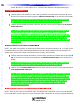
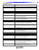
Master/Sla
ve System Connections
1 Make all connections for Status sensing, IR and RS232 Control, Switch Closures etc., per Section:
Connections. In addition:
2 Connect the RFX-250 RF sensor to the Master Controller.
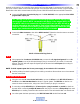
3 Connect a MS-01 Master/Sla
ve Cable (4-circuit, 3.5 mono mini plug cable, not included) between
Master IR/RS232 port 12 and Slave IR/RS232 port 12 as shown in.
4 Connect a RFX-250 connecting cable, (3-circuit, 3.5 mono mini plug cable, included) between
Master RF out mini jack and Slave RF in mini jack. (The RF In three pin plug terminal on the slave
can also be used for the RF
in connection on the sla
v
e end.)
5 Connect on 12 VDC 3.5A power supply (included) to each controller after all system connectsions
have been made and confirmed. Polarity: PIN=+12V; Sleeve=GND
Reference: Features and Parts