
Owner`s manual

78
Type in Section Title
U
S
I
N
G
C
C
P
E
D
I
T
O
R
T
O
P
R
O
G
R
A
M
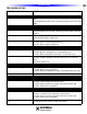
4 Be sure to test the RFX-250 location for RF interference as described in Section: RFX-250 installa-
tion.
5 Wire: Cat 5 or two conductor shielded 18 gauge; Max Wire Length: 200’
RF Out
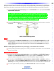
1 When using two MSC-400’s in a Master/Slave system, use one of the included 10’ 4-Circuit mini-
mini cables, to connect the RF out on the MSC-400 Master to the RF in on the MSC-400 Slave. The
RF out on the Master unit can also be connected to the RF in on a MRF-350 or MRF-300 for control
of devices located away from the MSC-400.
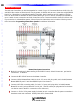
USB2 Keyboard Emulation
1 Using an appropriate USB cable, connect the USB2 port on the MSC-400 Rear Panel to a USB Port
on a PC. The remote is programmed with Aux code set 501 or Aux 502 (Keyboard commands). The
MSC-400 automatically routes Aux 501 or Aux 502 to the USB 2 port.
NOTE - This port cannot be used for programming the MSC-400.
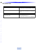
Relay 1
When connecting the MSC-400 Relays, the controlled device end may be terminated with a plug or connected
to wire terminals. In either case, the connections to the MSC Relays are the same for a given switch closure
configuration.
NO (Normally Open)
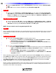
1 For a device that provides Voltage for use with a switch closure:
a) Connect the +V terminal on the controlled device
to the relay 1 no terminal
on the MSC-
400 rear panel, using one of the included three-pin plug-in connectors.
b) Connect the ground terminal on the controlled device to the Relay 1 Com terminal using
the same plug-in connector.
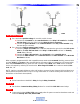
2 For a device that requires external control voltage.
a) Connect a jumper (24-14 AWG two conductor stranded wire, typical) from the 12V Out ter-
minal on the MSC-400 rear panel to the Relay 1 com terminal as shown in Normally Open
(Rela
y 2 Shown).
b) Connect the Relay 1 NO terminal to the +V terminal on the controlled device
c) Connect the GND terminal on the controlled device to the GND terminal on the MSC-400
rear panel as shown.
When a properly progr
ammed MSC-400 compatible remote sends an
On command, (latc
hing, momentary or
timed) Relay 1 will close and the controlled device will respond (turn on an amplifier or powered sub, raise a
lift, drop a screen, open or close drapes, etc). When the Off command (latching, press and hold or timed) is
sent, Relay 1will Open and the controlled device will respond (reverse previously switched mode). Wire
Gauge: 24-14 AWG two-conductor stranded; Max Load: 30V; .5A.
NO
TE
- Latc
hing commands initiate an action until another command is sent. Press and hold and timed com
-
mands perform the specified action only for as long as the button on a remote is held (press and hold) or for
the duration of the switch closure (timed).
Reference: Features and Parts