
Owner`s manual

66
Type in Section Title
U
S
I
N
G
C
C
P
E
D
I
T
O
R
T
O
P
R
O
G
R
A
M
GENERAL INFORMATION
MSC-400 MASTER SYSTEM CONTROLLER
The MSC-400 is the heart and brains of any home entertainment system. All system components, (RFX-250 RF
Sensor, Status Sensors, Emitters, RS232 Cables, and USB to Media Center Cables) are connected to the MSC-
400. It enables simple, reliable control and provides flexible, comprehensive connections that allow the seam-
less integration of any system device.
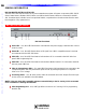
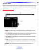
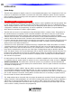
MSC-400 Front Panel Features
MSC-400 Front Panel
1 Power LED – One, blue LED illuminates to indicate MSC-400 power supply is attached and connect-
ed to AC power.
2 Status LED – One, blue LED flashes when an RF signal from a MSC compatible remote is received
and understood via the RFX-250 Sensor.
3 USB1 LED – One, blue LED illuminates to indicate that a PC is connected to the MSC-400 front
panel USB1 Programming Port.
4 USB2 LED – One, blue LED illuminates to indicate that a Media Center PC is connected to the MSC-
400 rear panel USB2 Port.
5 Video Or Voltage Sensor LEDS – Six, green LEDs illuminate to indicate that devices connected to the
corresponding MSC-400 rear panel sensor inputs are ON by sensing the presence of composite
video or AC or DC voltage.
6 IR Learning Sensor – One, IR sensor used to learn IR commands into a MSC Project File when a par-
ticular code is not a
v
ailable in the IR Database.
NOTE - Using one of the MSC-compatible remotes connected directly to the PC running CCS is recommend
ed for convenience in learning IR Commands.
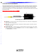
7 USB1 Programming Port – One, USB Type B Port connects to a PC running CCS for programming
the MSC-400.
Reference: Features and Parts