Owner’s Manual MRX-8 System Controller
Total Control MRX-8 Owner’s Manual ©2015 Universal Remote Control, Inc. The information in this owner’s manual is copyright protected. No part of this manual may be copied or reproduced in any form without prior written consent from Universal Remote Control, Inc. UNIVERSAL REMOTE CONTROL, INC. SHALL NOT BE LIABLE FOR OPERATIONAL, TECHNICAL OR EDITORIAL ERRORS/OMISSIONS MADE IN THIS MANUAL. The information in this owner’s manual may be subject to change without prior notice.
TABLE OF CONTENTS Introduction 1 Features and Benefits 1 Parts Guide 1 Front Panel Descriptions 2 Rear Panel Descriptions 3 Installing the MRX-8 4 Specifications 8 Limited Warranty Statement 9 End User Agreement 11 Federal Communication Commission Interference Statement 12 Declaration of Conformity 13
TOTAL CONTROL MRX-8 SYSTEM CONTROLLER Introduction Congratulations on purchasing the Total Control MRX-8 System Controller for automation and control. Using the Total Control line of interfaces provides you full access and control for every compatible device using IR, IP, RS-232, and Relays. This network based control is also compatible with URC sensors, like audio sensor and video sensor, which detects the status of a device and provides automation triggers.
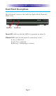
TOTAL CONTROL MRX-8 SYSTEM CONTROLLER Front Panel Descriptions The front panel consists of two indicator lights which illuminate when in use. Power LED Ethernet LED Power LED: Indicates that the MRX-8 is powered on when lit. Ethernet LED: Indicates the network connectivity status: ● On = Connected ● Off = Not connected ● Blinking = Attempting to connect.
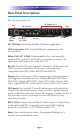
TOTAL CONTROL MRX-8 SYSTEM CONTROLLER Rear Panel Descriptions The rear panel ports are: LAN DC 12V Power IR Outputs: #1-6 Reset RS-232 Ports Relay: NO, NC, COM Sensors RFTX-1 DC 12V Power: Attach the included 12V power supply here. LAN Connection: RJ45 standard Ethernet connection to the local network. Relays (NO, NC, COM): Programmable relay to be normally opened (NO), normally closed (NC) or momentary contact. An application shall require less than 30V/.5A.
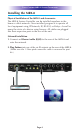
TOTAL CONTROL MRX-8 SYSTEM CONTROLLER Installing the MRX-8 Physical Installation of the MRX-8 and Accessories The MRX-8 System Controller can be installed anywhere in the home or office network. Once installed, program it to operate all local equipment using IP/Network, IR, RS-232, or Relays. As well as query the status of a device using Sensors. All cables are plugged into their respective ports in the rear of the unit. Network Installation 1.
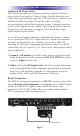
TOTAL CONTROL MRX-8 SYSTEM CONTROLLER Optimizing IR Flasher Levels Test a few commands for each device before fixing the flasher in place on the front panel of a device. Since Satellite Receivers and Cable Boxes are extremely sensitive to IR overload or saturation, you should test them thoroughly. Put up the cable or satellite on-screen guide and test the navigation arrows. Compare operation via RF to the original remote control. Operation should be identical.
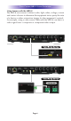
TOTAL CONTROL MRX-8 SYSTEM CONTROLLER Using Sensors with the MRX-8 The MRX-8 uses sensors to detect audio, light, video, voltage, current and contact closures to determine the equipment status, query the state of a device or other automation triggers for the equipment it controls. For example, using a video sensor cable with the MRX-8 can detect a video signal from a composite or component video output.
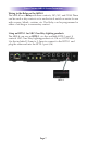
TOTAL CONTROL MRX-8 SYSTEM CONTROLLER Wiring to the Relay on the MRX-8 The MRX-8 has a Relay with three contacts, NO, NC, and COM. These can be used as dry contacts or to an electrical switch or motor for use with screens, blinds, curtains, etc. The Relay can be programmed as either a latching or a momentary contact. Using an RFTX-1 for URC One-Way Lighting products The MRX-8 can use an RFTX-1, via the available RFTX-1 port. It controls URC One-Way Lighting products at 418 or 433.92 MHz.
TOTAL CONTROL MRX-8 SYSTEM CONTROLLER Specifications Network: One 10/100 Ethernet port Relay: One relay configurable to be NO, NC or Momentary Sensor: Two Sensors support Video (SEN-VID), Voltage (SEN-VOLT), Audio (SEN-AUD), Current (SEN-CMF), Light (SEN-LITE), and Contact Closure (SEN-CCLS) sensors. RS-232: Two RS-232 ports support TX, RX and GND two-way communication via URC cables.
TOTAL CONTROL MRX-8 SYSTEM CONTROLLER Limited Warranty Statement 1. Limited Warranty and Disclaimers Universal Remote Control, Inc. (“URC”) warrants that the URC equipment shall be free from defects in material and workmanship under normal usage for two (2) years from purchase when such is purchased from URC. This limited warranty is valid only in the United States of America.
TOTAL CONTROL MRX-8 SYSTEM CONTROLLER SKILL AND CARE, OR OUTCOME OR RESULTS. WITHOUT IN ANY WAY LIMITING THE GENERALITY OF THE OTHER PROVISIONS HEREIN, WARRANTY DOES NOT COVER: (I) DAMAGE FROM MISUSE, NEGLECT OR ACTS OR NATURE, (II) MODIFICATIONS, (III) INTEGRATION WITH THIRD PARTY CONTENT (IV) BEYOND THE WARRANTY PERIOD AND/ OR FAILURE TO FOLLOW URC WARRANTY CLAIM PROCEDURE.
TOTAL CONTROL MRX-8 SYSTEM CONTROLLER URC’s PC programmable remotes or any of our Total Control® whole-house equipment are authorized for online internet sales. Buying URC’s PC programmable remotes or any of our Total Control® whole-house equipment online means buying equipment that does not have a URC’s limited warranty. Such equipment is not eligible for URC tech support or software support, either. 2.
TOTAL CONTROL MRX-8 SYSTEM CONTROLLER Federal Communication Commission Interference Statement This equipment has been tested and found to comply with the limits for a Class B digital device, pursuant to part 15 of the FCC Rules. These limits are designed to provide reasonable protection against harmful interference in a residential installation.
TOTAL CONTROL MRX-8 SYSTEM CONTROLLER Declaration of Conformity Company Name : OH SUNG ELECTRONICS CO., LTD.
NOTE Page 14
NOTE Page 15
500 Mamaroneck Avenue, Harrison, NY 10528 Phone: (914) 835-4484 Fax: (914) 835-4532 www.universalremote.