KP-4000 Installation Manual Network Keypad
KP-4000 Installation Manual ©2010 Universal Remote Control, Inc. The information in this manual is copyright protected. No part of this manual may be copied or reproduced in any form without prior written consent from Universal Remote Control, Inc. UNIVERSAL REMOTE CONTROL, INC. SHALL NOT BE LIABLE FOR OPERATIONAL, TECHNICAL OR EDITORIAL ERRORS/OMISSIONS MADE IN THIS MANUAL. The information in this manual may be subject to change without prior notice.
TABLE OF CONTENTS Introduction 1 Features and Benefits 2 Parts Guide 2 Network Requirements and Power Options 3 Installation Notes 5 MAC Address Labels/Reset Button 5 Connections 5 IR OUT/RFTX-1 6 12V Power 7 In-Wall Installation 8 CCP MAC Address Discovery 9 Displaying the Settings Screen 10 Adjusting Sleep Settings 10 Button Light Settings 10 Setting Date and Time 10 Sound 11 Adjusting Brightness 11 System 11 Network 11 Factory Default 12 Exit 12 Frequently Asked
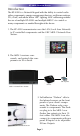
KP-4000 NETWORK KEYPAD Introduction The KP-4000 is a Network Keypad with the ability to control audio video components, energy management devices, multizone matrixes, PCs, iPods, and whole house URC Lighting. MAC addressing enables the use of multiple KP-4000’s and multiple MRX-1’s to control as many components as needed throughout the house. 1. The KP-4000 communicates over the LAN (Local Area Network) to IP controlled components and the URC MRX-1 Network Base Station. 2.
KP-4000 NETWORK KEYPAD Features and Benefits 2-Way IP and RS-232 Home Theater AVRS Via the unique URC 2-Way database, installers can drag and drop 2-Way pre-programmed modules into any KP-4000 for multi-zone receivers with either IP or via the MRX-1, RS-232 control.
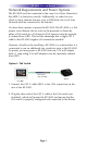
KP-4000 NETWORK KEYPAD Network Requirements and Power Options The KP-4000 must be connected to the same Local Area Network as the MRX-1 to function correctly. Additionally, in order for your client to enjoy internet features such as RSS feeds, the Local Area Network must be connected to the Internet. You have three options to power the KP-4000.
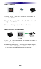
KP-4000 NETWORK KEYPAD Option 2: PoE Injector PoE Injector (not included) Router KP-4000 1. Connect the CAT 5 cable (RJ45) to the LAN connection on the rear of the KP-4000. 2. Plug the other end of the CAT 5 cable to the PoE Injector which will power the KP-4000. 3. Connect the PoE injector (not included) to the Router. Option 3: No PoE: 12 Volt Power Supply Power Supply (not included) Router KP-4000 1. Splice a 12V 1Amp Power Adapter (not included) and connect to the rear Power input. 2.
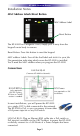
KP-4000 NETWORK KEYPAD Installation Notes MAC Address Labels/Reset Button MAC Address Label Reset Button The KP-4000 has a magnetic cover, simply pull it away from the keypad’s main body to remove. Reset Button: Press this button to reset the keypad. MAC address Labels: Tear off the 2nd label and stick it to your Job Documentation indicating which room the KP-4000 is installed. You’ll need the MAC address when you program the KP-4000.
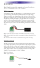
KP-4000 NETWORK KEYPAD IR OUT/RFTX-1 This 3 Conductor removable connector can be used for either an RFTX-1 RF transmitter or for a URC IR emitter. RFTX-1 Connections In installations with URC RF lighting or a standard RF base station, you will need to add an RFTX-1 RF Transmitter to the KP-4000. Range can wildly vary, depending on the structure of the wall the KP-4000 is installed in.
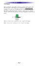
KP-4000 NETWORK KEYPAD 12V Power This 2 conductor removable connector can be used to power the KP-4000 with a wall adapter in an installation where PoE is not available. You must run an additional two conductor cable to the KP-4000 to utilize this feature. Connect a spliced power adapter 12Volt, 1AMP with the polarity (Positive & Negative) connected correctly. - + 12V 1A – Connect to the + conductor of a 12V, 1 Amp DC wall adapter. GND – Connect to the – conductor of a 12V, 1 Amp DC wall adapter.
KP-4000 NETWORK KEYPAD In-Wall Installation Magnetic cover plate KP-4000 Two-Gang Wall Box 1. The KP-4000 installs in a standard two gang box. If in a retrofit installation, cut in and install a standard two gang p-ring or retro fit box (not included) into the wall. 2. Make connections for IR Out/RFTX-1, LAN, or Power Supply. For connections, refer to page 5. 3. Next, secure KP-4000 onto p-ring or retro fit box with the 4 included screws. 4.
KP-4000 NETWORK KEYPAD CCP MAC Address Discovery 1.Once the KP-4000 has been connected to the network, notate the MAC address located on the KP-4000 under the magnetic cover plate. 2. Open the Complete Control Program editor. 3. Select the Program tab then press Configure Home. 4. Add a KP-4000 Network Keypad from the Remotes section and the properties window opens. Note: Adding a MRX-1 base station to communicate with a KP-4000 is recommended. 5.
KP-4000 NETWORK KEYPAD Displaying the Settings Screen You can adjust the settings of the KP-4000 whenever you like by pressing and holding both the MAIN and MUTE buttons for five seconds. When you do, the screen will change to the SETTINGS screen. If you do not press any button on the SETTINGS screen within 1 minute, the KP-4000 will time out and automatically return to normal operation. Adjusting Sleep Settings Conserve energy by configuring the keypad to fall asleep after a specified amount of time.
KP-4000 NETWORK KEYPAD Sound Your KP-4000 may have been programmed to make sounds. This is optional, and some professional installers may prefer to keep it silent. However, you can adjust the volume to any level you like by touching and dragging the volume control here. Adjusting Brightness Simply touch and drag the brightness slider to the desired level. System The System Information screen displays data about your KP-4000’s operating system, memory etc.
KP-4000 NETWORK KEYPAD Factory Default WARNING! Only use this button when instructed to by Technical Support. It resets the memory of the KP-4000 to the factory condition. All your programming will be lost! Exit When you have finished adjusting Settings, simply tap the EXIT button to return to normal operation.
KP-4000 NETWORK KEYPAD Frequently Asked Questions I am unable to control my URC Lighting Dimmer/Switch with the KP-4000. Now what? Make sure the RF switch on the RFTX-1 is set to the correct frequency for the URC Dimmer or Switch. URC Lighting Models MRFA is 418MHz and MRFB is 433MHz. How do I update the firmware? Periodically there will be firmware updates for the KP-4000. Make sure it is connected to the Network then open CCP and click on the Live Update button located within the Communications tab.
KP-4000 NETWORK KEYPAD USA Limited Warranty Statement Your Universal Remote Control, when delivered to you in new condition, is warranted against defects in materials or workmanship as follows: UNIVERSAL REMOTE CONTROL, INC. warrants this product against defects in material or workmanship for a period of one (1) year and as set forth below.
KP-4000 NETWORK KEYPAD Federal Communication Commission Interference Statement This equipment has been tested and found to comply with the limits for a Class B digital device, pursuant to part 15 of the FCC Rules. These limits are designed to provide reasonable protection against harmful interference in a residential installation.
MEMO Page 16
500 Mamaroneck Avenue, Harrison, NY 10528 Phone: (914) 835-4484 Fax: (914) 835-4532 www.universalremote.com OCE-0080A Rev.