
User guide

139
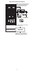
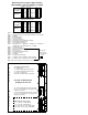
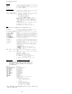
Distributed Processing Peripheral (DPP)
(MD’d 4Q00; replaced with SBA on SDM)
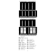
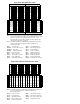
A Chassis (Processor A)
B Chassis (Processor B)
6M60 — Quad SIO
6M62 — Central Processor Unit with Direct Memory Access (DMA)
6M63 — EPROM
6M64 — Extended Memory
6M65 — Error Control II
6M66 — Disk Drive Interface
6M68 — Bus Terminator (permanently mounted)
6M70 — Data Stream Interface (DSI)
6M71 — Power Supply Assembly
6M72 — Disk Drive; AA = 72MB; BA = 140MB; CA = 30MB; DA =
380MB; DD = 380 MB Turbo; EA = 760MB
6M94 — 56 Kbps Interface
M609 — Error Control Jumper
6M72 — Disk II Crossover CP
6M93 — Disk Crossover
6M84 — Power/Alarm Communication
6M48 — 56 Kbps Crossover
6M56 — Fan Filter
6M54 — 56 Kbps Mounting Panel
6M73 — 56 Kbps Crossover Interface Cable Assembly
6M85 — 56 Kbps Crossover Interface Cable Assembly
Note: DIP switch settings can be found in NTP 297-1001-539.
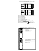
6M71
Power Supply
Assembly
6M72
Disk Drive
6
M
62
01
6
M
63
F
02
6
M
64
R
03
O
04
6
M
65
N
05
6
M
60
T
06
6
M
94
07
V
08
I
09
E
10
6
M
66
W
11
6
M
70
12
6
M
70
13
6
M
68
14
6M71
Power Supply
Assembly
6M72
Disk Drive
6
M
62
01
6
M
63
F
02
6
M
64
R
03
O
04
M
6
09
N
05
6
M
60
T
06
6
M
94
07
V
08
I
09
E
10
6
M
66
W
11
6
M
70
12
6
M
70
13
6
M
68
14
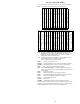
J1
J2
J3 J4
J14
J11 J12
J9
J10
J13
M
T
D
M
T
D
A
C
H
A
S
S
I
S
B
C
H
A
S
S
I
S
4-Channel Communication
J1 = Polling link
J2 = Human Machine Interface Link 1
J3 = Human Machine Interface Link 2
J4 = EAT or Printer Port
(Emergency Administrative Terminal)
J9 = Data Stream Interface (DSI) 0 located
in slot 13; A and B Chassis (Assigned to the
J10 = Data Stream Interface (DSI) 1 located
in slot 12; A and B Chassis (Assigned to the
J11 = V.35 Link 1 (56K Polling)
J12 = V.35 Link 2 (56K Polling)
J13 = RS-232 Link 1 (up to 9600 Baud)
J14 = RS-232 Link 2 (up to 9600 Baud)
56K Connector Turbo “Only”
Magnetic Tape Drive
Left side of DPP Chassis
looking from the side
Magnetic Tape Drive
These packs
are located in
the back of the
DPP