
User guide

122
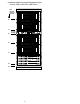
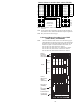
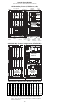
Outside Plant Access Cabinet
(NTP 297-8211-550, OPAC Maintenance Manual)
Note: BCC0 & 1 are NT8X02XX Battery Charging Controller packs.
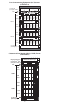
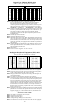
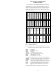
RLCM/OPM Host Interface Equipment (HIE) shelf
Note: * Provisioned for Emergency Stand-alone (ESA) Mode. Equipped
with two 6X47AB 2MB cards or one 6X47AC 4MB memory card.
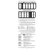
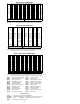
OPAC Remote Maintenance Module (RMM) shelf
Note: For further description of the following RMM and HIE packs, see
the “Circuit Pack Description” within this QRG or see
NTP 297-8991-805.
Note: For RMM circuit numbers for cards in slots 03 thru 16, see the
RMM shelf located with the MTM shelf within this QRG.
0X10 —Scan Card 3X09 — Metallic Test Access (MTA)
2X06 — Power Converter 6X27 — PCM30 Interface
2X09 — Power Converter 6X45 — ESA Processor
2X10 — MTU Analog card 6X47 —ESA Memory
2X11 —MTU Digital card 6X50 — DS1 Interface
2X48 — Digitone Receiver 6X57 — Signal Distribution Type 1
2X57 —Sig. Dist. (SD) 6X60 — RLCM/OPM Ringing Generator
2X59 — Group CODEC 6X73 — RIM Link Control
2X70 — Power Converter 6X74 — RMM/RIM Control
2X90 — Test Trunk Card 6X75 —ESA Clock and Tone
6
X
60
01
R
I
N
G
I
N
G
G
E
N
E
R
A
T
O
R
6
X
60
05
R
I
N
G
I
N
G
G
E
N
E
R
A
T
O
R
0
X
50
09
0
X
50
10
0
X
50
11
0
X
50
12
0
X
50
or
6
X
47
*
13
0
X
50
or
6
X
47
*
14
0
X
50
or
6
X
45
*
15
0
X
50
or
6
X
75
*
16
6
X
73
17
6
X
73
18
6
X
50
or
6
X
27
19
6
X
50
or
6
X
27
20
6
X
50
or
6
X
27
21
2
X
70
22
P
O
W
E
R
2324
2
X
70
25
P
O
W
E
R
2627
2
X
59
G
C
01
6
X
74
C
N
T
L
02
2
X
10
M
T
U
(a)
03
2
X
11
M
T
U
(d)
04
3
X
09
M
T
A
05
3
X
09
R
M
T
A
06
0
X
10
S
C
A
N
07
0
X
10
S
C
A
N
08
2
X
90
T
E
S
T
09
2
X
90
T
E
S
T
10
2
X
48
D
G
T
11
2
X
48
D
G
T
12
F
I
L
L
E
R
13
F
I
L
L
E
R
14
F
I
L
L
E
R
15
F
I
L
L
E
R
16
2
X
09
17
P
O
W
E
R
18
F
I
L
L
E
R
19
2
X
06
20
P
O
W
E
R
21 22
Host
Interface
Equipment
Remote
Maintenance
Module
BCU
Cooling unit Cooling unit
Rectifiers
Filler panel
PO747175
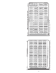
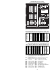
LCM
L
D
0
L
CA
-
0
L
CA
- 1
L
D
1
L
D
2
L
D
3
L
D
4
L
D
5
L
D
6
L
D
7
L
D
8
L
D
9
B
C
C
0
B
C
C
1
BAY 1BAY 0
MSP