
User guide


112
SPM Log References
Use SPM logs SPM300 thru SPM710 and other related logs: SPRF670 -
671; CARR300, 310, 500, 510, 511, 512, 800, 810, 811; ENET211, 308,
311; PRSM400.
SPM Alarms
Note: If your office is pre-NA011 and you have a non-node visible
alarm, (such as a PROTFAIL), you must use logutil and/or
dlog/scanlog to locate an SPM331 log indicating the source of
the alarm. The only way to clear a “Non-Node Visual” SPM
alarm is to perform a successful Protection Switch of the RM
causing the alarm.
Note: In NA011 and above offices you can list all SPMs with alarms,
INCLUDING the ones caused by protection switching alarms by
entering >
MAPCI NODISP;MTC;MTC;POST SPM ALL
and
then enter >QUERYPM FLT ALL.
Note: Tables MNPRTGRP, MNCKTPAK, MNNODE, and MNH-
SCARR, contain alarm datafill.
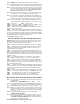
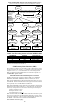
LED Alarm Indicators
Note:
For a detailed description of the alarm LED indicators for the frame
and RMs, see NTP 297-1771-550, SPM Hardware Maintenance
Reference Manual.
The following table provides a quick reference for RM LED status and
what their indication means.
Note: To prolong LED life, program the green LEDs so it can enter the
sleep mode. LED sleep-mode timing is controlled by the entry in
field LEDTIMER in data schema table MNNODE. Sleep mode
does not apply to red LEDs.
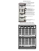
PREPDATACHNG Command
Prior to BAS18 core offices, in order to perform SPM resource manipula-
tion in table MNCKTPAK, the craft person needed to have an understand-
ing of the concept of "Roving Spare Strategy", and may have to perform
several sparing actions (prot switches) in order to align the RMID and
PROTWHOMID and change the RM's Resource Datafill properly.
In BAS18 and above, the PREPDATACHNG command will reduce the
complexity/difficulty of provisioning, configuring, and changing the
Resource Datafill on RMs. The user will only need to issue a command
(PrepDataChng) to align the RMID and PROTWHOMID of the RM in
context. Depending on the result of this command, the customer will be
notified if they can proceed to change the RM datafill and finally RTS the
RM.
To invoke this command:
>mapci;mtc;pm;post spm <#> ; select <DSP or VSP to be modified in
MNCKTPAK>
>PrepDataChng
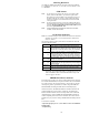
LED Status Indication and Action
Green Red
Off Off
Green LEDs are in sleep mode (module can also be not
powered or not seated). When all LEDs are off, there are no
critical faults and an indicator test is not underway. Use an
indicator test to check LED function. Also, see note below
Green Red
On On
A power on self test (POST) or an LED indicator test is
underway. During a POST, the LEDs are controlled by the
initial boot loader (IBL) software. If both LEDs remain on for
an extended period after a POST, the module is defective.
For detailed instructions for replacement, see the appropri-
Green Red
On Off
Normal operation—there are no critical faults and no action
is required. Do not remove a module displaying this alarm
indication or combination.
Green Red
Off On
Critical fault—replace the module. For detailed instructions
for replacement, see the appropriate NTP for Card Replace-
ment Procedures.
Amber Off
Normal operation—all external signal inputs to the module
faceplate are valid.
Amber On
At least one external signal source entering the module
faceplate is not carrying a valid signal.