
User guide


106
SPM Quick References
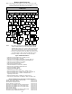
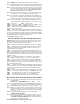
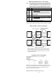
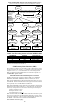
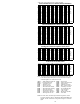
SPM Frame Layout for a 4-slot High-Speed Backplane
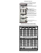
DMS-Spectrum Peripheral Module (SPM)
(
NTP 297-1771-550 Hardware Maintenance Reference Manual
)
Note: Configuration is for a NTLX51BA 4 high-speed slot (4HSS) SPM.
DMS-SPM Module continue on the next page.
NTLX57XX Power Control Interface (PCI) Unit
Cooling Unit (NTLX56XX Fan Units)
FAN 1 FAN 2 FAN 3 FAN 4
RM
1-S
DLC
LX
72
for
PRI
01
RM
1-S
DLC
LX
72
for
PRI
02
RM
3-S
VSP
or
DSP
03
RM
3-S
VSP
or
DSP
04
RM
3-S
VSP
or
DSP
05
RM
3-S
VSP
or
DSP
06
RM
1-S
DLC
LX
72
for
PRI
07
RM
1-S
DLC
LX
72
for
PRI
08
RM
3-S
VSP
or
DSP
09
RM
3-S
VSP
or
DSP
10
RM
3-S
VSP
or
DSP
11
RM
3-S
VSP
or
DSP
12
RM
3-S
VSP
or
DSP
13
RM
3-S
VSP
or
DSP
14
SIM
B
LX
61
P
W
R
15
RMID Slot Numbers below for this shelf are:
15 16 17 18 19 20 21 22 23 24 25 26 27 28 n/a
SHELF 1 (Front View)
Cable Area
RM
9-S
ATM
LX
73
01
RM
9-S
ATM
LX
73
02
RM
3-S
VSP
or
DSP
03
RM
3-S
VSP
or
DSP
04
RM
3-S
VSP
or
DSP
65
RM
3-S
VSP
or
DSP
06
CE
M
#0
LX
82
CE
M
#1
LX
82
RM
9-S
OC3
LX
71
09
RM
9-S
OC3
LX
71
10
RM
3-S
VSP
or
DSP
11
RM
3-S
VSP
or
DSP
12
RM
3-S
VSP
or
DSP
13
RM
3-S
VSP
or
DSP
14
SIM
A
LX
61
P
W
R
15
Note: Physical and RMID Slot Numbers are the same on this shelf
SHELF 0 (Front View)
Cable Area
Air Filter Tray (NTLX5016) & Air Filter (NTLX5015)
The Power Cabling Interface Unit
(PCIU) contains the:
Alarm Indicator Lamps
Fan Failure Lamp
Cooling Unit (Four fans per individual
alarm) (Alm LED on left of each fan)
Shelf Trough and Cable Area
SPM 1 Shelf 0 equipped for two
Common Equipment Modules (CEMs),
two OC-3 Interface Modules,
Shelf Interface Module (SIM), and
Resource Modules (see layout below)
Shelf Trough and Cable Area
Air Filter (NTLX5015) Pt # A0665487
Upper Grill Shelf Assembly (Includes
Test Lamp and Data and Tel Jacks)
Cooling Unit (Four fans per individual
alarm) (Alm LED on left of each fan)
Shelf Trough and Cable Area
Shelf Trough and Cable Area
Air Filter (NTLX5015) Pt # A0665487
Lower Grill assembly
SPM 0
Shelf 1
SPM 1
Shelf 1
SPM 0
Shelf 0