
Installation guide

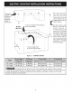


ELECTRIC
COOKTOP
INSTALLATION
INSTRUCTIONS
Important
Notes
to
the
Installer
|.
Read
all
instructions
contained
in
these
installation
instructions
before
installing
the
cooktop.
2.
Remove
ali
packing
material
before
connecting
the
electrical
supply
to
the
cooktop.
3.
Observe
all
governing
codes
and
ordinances.
4.
Be
sure
to
leave
these
instructions
with
the
consumer.
important
Note
to
the
Consumer
Keep
these
instructions
with
your
Use
and
Care
Guide
for
future
reference.
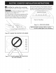
IMPORTANT
SAFETY
INSTRUCTIONS
Be
sure
your
cooktop
is
installed
and
grounded
properly
by
a
qualified
installer
or
service
technician.
*
These
cooktops
must
be
electrically
grounded
in
accordance
with
local
codes
or,
in
their
absence,
with
the
National
Electrical
Code
ANSI/NFPA
No.
70—latest
edition
in
the
United
States.
(NWN
te]
The
electrical
power
to
the
cooktop
must
be
shut
off
while
line
connections
are
being
made.
Failure
to
do
so
could
result
in
serious
injury
or
death.
Electrical
Requirements
Observe
all
governing
codes
and
local
ordinances.
1.
A
3-wire
or
4-wire
single
phase
120/240
or
120/208
Volt,
60
Hz
AC
only
electrical
supply
is
required
on
a
separate
circuit
fused
on
both
sides
of
the
line.
A
50A
minimum
time-delay
fuse
or
circuit
breaker
is
needed.
DO
NOT
fuse
neutral.
NOTE:
Wire
sizes
and
connections
must
conform
with
the
fuse
size
and
rating
of
the
appliance
in
accordance
with
the
National
Electrical
Code
ANSI/NFPA
No.
70-latest
edition.
PNW
iit)
An
extension
cord
must
not
be
used
with
this
appliance.
Such
use
may
resulf
in a
fire,
electrical
shock,
or
other
personal
injury.
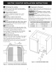
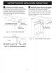
2.
The
appliance
should
be
connected
to
the
fused
disconnect
(or
circuit
breaker)
box
through
flexible
armored
or
nonmetallic
sheathed
cable.
The
flexible
armored
cable
extending
from
this
appliance
should
be
connected
directly
to
the
grounded
junction
box.
The
junction
box
should
be
located
as
shown
in
Figure
4
with
as
much
slack
as
possible
remaining
in
the
cable
between
the
box and
the
appliance,
so
it
can
be
moved
if
servicing
is
ever
necessary.
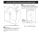
3.
A
suitable
strain
relief
must
be
provided
to
attach
the
flexible
armored
cable
to
the
junction
box.
Observe
all
governing
codes
and
local
ordinances.
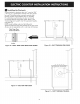
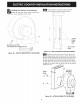
Serial
Plate
Location
Model
and
Serial
Plate
(Under
Cooktop)
Figure
3
Required
Tools
for
Installation
-
Phillips
Screwdriver
-
Va"
Nut
driver
/
Ratchet
-
7/6"
Nut
driver
/
Ratchet
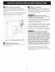
Supplied
Hardware
4
(@)
1/4-20
Nylon
Insert
4)
<i
7/16"
Hex
Nut
Blower
(fig.
19)
vammmm
10-24
3.5"
Brackets
(2)
I
ong
Phillips
Screw
(fig.
15
&
16)
#8-18
Wide
Head
Phillips
Screw
#8-18
Black
4"
Hex
Head
Screw
Transition
Duct
(fig.
20)
Plenum
and
Wire
Box
(fig.
17
&
21)
Countertop
(fig.
15
&
16)
Hold
Down
Bracket
Plastic
Access
Hole
Plug
=
Plenum
(fig.
17}