ELECTRIC COOKTOP INSTALLATION INSTRUCTIONS INSTALLATION AND SERVICE MUST BE PERFORMED BY A QUALIFIED INSTALLER. IMPORTANT: SAVE FOR LOCAL ELECTRICAL INSPECTOR'S USE. READ AND SAVE THESE INSTRUCTIONS FOR FUTURE REFERENCE. U.S.A. PUNTER FOR YOUR SAFETY: DO NOT store or use gasoline or other flammable vapors and liquids in the vicinity of this or any other appliance.
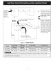
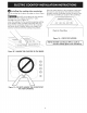
ELECTRIC COOKTOP INSTALLATION INSTRUCTIONS a Overhead Cabinet wasted Should Not exceed x Maximum Depth of 13" (33 cm) 30" <—— (76.2 cm) Min. Clearance Between the Top of the Cooking Platform _ and the Bottom of an Unprotected Wood or / ee * 18" Min. Metal Cabinet. 1" (2.5 cm) Minimum Flat Distance 24" (61 cm) Min. when from Cutout Edge. Bottom of Wood or Metal Cabinet is Protected by Not (45.7 cm) Less Than 1/8" Flame Retardant Millboard Covered With Not Less Than No. 28 MGS Sheet (0.
ELECTRIC COOKTOP INSTALLATION INSTRUCTIONS Important Notes to the Installer |. 2. 3. 4. Read all instructions contained in these installation instructions before installing the cooktop. Remove ali packing material before connecting the electrical supply to the cooktop. Observe all governing codes and ordinances. Be sure to leave these instructions with the consumer. can be moved if servicing is ever necessary.
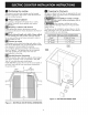
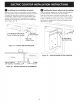
ELECTRIC COOKTOP INSTALLATION INSTRUCTIONS @ Positioning the cooktop Preparing for Ductwork The exhaust vent from the cooktop must be located between wail studs or floor joists so that the ductwork may be installed properly Cut hole in cabinet wali or floor as appropriate for your installation. Make sure exhaust duct is located between wail studs or floor joists. & DO NOT vent into a wall, ceiling, crawlspace, attic or any concealed space.
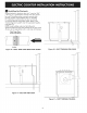
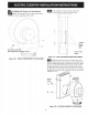
ELECTRIC COOKTOP INSTALLATION INSTRUCTIONS CUTOUT CENTER— © 7 I CUTOUT CENTER — , ; \ ) S \ Blower to Ductwork Alignment The use of flexible ducting is discouraged because it can severely restrict airflow. If the blower outlet and the floor or wall duct location DO NOT align, then flexible METAL ducting can be used to adapt to an offset. Sg FF e906 GPeeGeG ] ee ee ee ee Com Com Comer omer 2 eo 8 GGG G& Ee EE ome Lome Gorm Comes 6" Max. | Center line To Center line Offset S\ Figure 6 — BACK WAL
ELECTRIC COOKTOP INSTALLATION INSTRUCTIONS Installing the Ductwork | oO Use galvanized or aluminum duct in 6” round or 3V4” x 10" size, or a combination of both. PVC duct should be used if installing under a poured concrete slab. Use the shortest and straightest duct run possible. For satisfactory performance, the duct run should not exceed 100 feet equivalent length. Refer to the “Calculating Duct Length” chart for equivalent lengths. (see page 13).
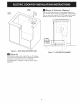
ELECTRIC COOKTOP INSTALLATION INSTRUCTIONS 6 Installing the cooktop into countertop Lift the cooktop by the glass side edges as shown Figure 12. DO NOT use the glass top vent opening to lift or move the cooktop into position — glass breakage may occur (Figure 13). Lower the cooktop into the countertop opening, guiding it into position. Glass is fragile——-DO NOT allow it to drop onto the countertop. Support from the underside and lower slowly.
ELECTRIC COOKTOP INSTALLATION INSTRUCTIONS & Installing the installation brackets © Remove the two screws in the bottom of the cooktop near the center of each of the ends. Use the two screws to attach the hold down brackets to the bottom of the cooktop. Insert the screw into the bracket until it contacts the backside of the countertop, to prevent damage to the countertop, DO NOT over tighten the : screw. Figure 15 & 16.
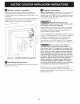
ELECTRIC COOKTOP INSTALLATION INSTRUCTIONS © cre Installing the blower to the plenum Attach Insert 4 plastic access hole plugs from the outside of the plenum to seal the access holes. the transition to the outlet of the blower “} — | | | using four screws. Tape the joint to seal. Pom | | l = l- — | oi oe 1/4-20 Me aa Insert —— One Screw per Side. #8-18 Wide Head — : Nylon Nut a ~.
ELECTRIC COOKTOP INSTALLATION INSTRUCTIONS © Blower electrical connection Connect the 5-pin plug on the blower assembly to the matching 5-pin receptacle on the bottom of the cooktop, making sure to engage the locking tabs on the connectors. Fold all wires into the wire box on the end of the blower conduit. Fasten the wire box to the cooktop with two #8-18 making sure that no wires are trapped.
ELECTRIC COOKTOP INSTALLATION INSTRUCTIONS lf the appliance is used in a new branch circuit installation (1996 NEC), mobile home, recreational vehicle, or where local codes DO NOT permit grounding through the nevtral (white) wire, the appliance frame MUST NOT be connected fo the neutral wire of the 4-wire electrical system. Fite] (if your appliance is equipped with a white neutral conductor.) This appliance is manufactured with a white neutral power supply and a frame connected copper wire.
ELECTRIC COOKTOP INSTALLATION INSTRUCTIONS ® Install Grease Filter and Grate Carefully place the vent grate onto the opening. Place the side of the vent marked FRONT towards the front of the opening. The vent grate will only fit one way, DO NOT force into the opening. DO NOT operate the vent without the grease filter in place. * Place the grease filter diagonally through the vent * opening. Make sure it rests, at an angle, on the supports in the vent opening. A “iAl .
ELECTRIC COOKTOP INSTALLATION INSTRUCTIONS Calculating Duct Length Table For maximum efficiency, use the shortest and straightest duct possible. Use as few fittings as possible. For best performance, the duct run should not exceed 100 feet of equivalent length. Calculations are approximate and based on HVAC industry standards. DUCT EQUIVALENT LENGTH X PIECES 6" (15.2em) Round Straight * (_) Oo) 6" (15.2cm) Round Metal Flex he NUMBER USED = EQUIVALENT LENGTH 1 Fe (0.3m) Ft orm 1.5 Ft. (0.
NOTES 14