
Installation guide

Installation Instructions
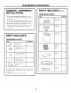
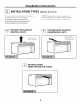
HOOD EXHAUST
NOTE: Read these next two pages only if you plan to vent your exhaust to the
outside. If you plan to recircnlate the air back into the room, proceed to page 6.
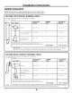
OUTSIDE TOP EXHAUST (EXAMPLE ONLY)
The following chart describes an example of one possible
ductwork installation.
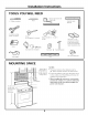
DUCT PIECES
[]
Roof Cap
12Ft,(3,6m)StraightDuct
(6'715,2cmRound)
EQUIVALENT NUMBER EQUIVALENT
LENGTH x USED = LENGTH
Rectangular-to-Round
TransitionAdaptor*
24 Ft,(7,3m) x (1)
12Ft,(3,6m) x (1)
[]
5 Ft, (1,5m) x
Equivalentlengthsof ductpiecesare basedon actualtests and
reflect requirementsfor goodventingperformancewith anyventhood,
(1)
24 Ft,(7,3m)
12Ft,(3,6m)
5 Ft, (1,5m)
Total Length = 41 Ft. (12.5 m)
* IMPORTANT: If a rectangular-to-round transition adaptor is used, the bottom corners of the damper
will have to be cut to fit, using the tin snips, ira order to allow fi'ee movement of the damper'.
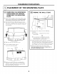
OUTSIDE BACK EXHAUST (EXAMPLE ONLY)
The following chart describes an example of one possible
ductwork installation.
EQUIVALENT
DUCT PIECES LENGTH* x
_[_ Cap (12,2m) x
Wall 40Ft,
3 Ft,StraightDuct 3 Ft,(0,9m) x
(31/g'x 10'78,2x25,4cm
_- Rectangular)
90° Elbow 10Ft, (3m) x
NUMBER
USED
(1)
(1) =
(2) =
EQUIVALENT
LENGTH
40Ft, (12,2m)
3 Ft,(0,9m)
20Ft, (3m)
Equivalentlengthsof ductpiecesarebasedonactualtestsand
reflect requirementsfor goodventingperformancewith anyvent hood,
Total Length = 63 Ft. (19.2 m)
NOTE: For back exhaust, care should be taken to align exhaust with space between studs, or wall should be prepared
at the time it is constructed by leaving enough space between the wall studs to accommodate exhaust.
10