
User guide

Link to Table of Contents
User Guide
219
ULS Reference Guide Book
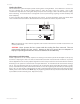
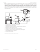
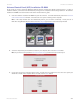
Note: The following diagram shows a typical exhaust system layout. Use this as a guideline for proper exhaust
system installation. Although this diagram serves as an example, we recommend you consult with a licensed
contractor to meet local safety and building code requirements and to also calculate the correct size blower
required for your particular installation. Length of exhaust pipe, exhaust pipe diameter, number of 90-degree
angles and other restrictions must be calculated when determining the correct exhaust blower unit. Installing an
undersized or oversized blower is not only unsafe, but can also lead to excessive wear and tear to the laser system
and premature failure.
Exhaust blower mounted outside* (User Supplied)1.
Weatherproof shield (User Supplied)2.
Rigid ducting matching the diameter of the blower inlet (User Supplied)3.
Shut-o or air-ow gate (User Supplied)4.
Adapter to the hose reduces from 4” to 3” (User Supplied)5.
Flexible, wire-reinforced, industrial grade rubber hose (User Supplied)6.
Exhaust On/O swtich (User Supplied)7.
Computer (User Supplied)8.
1
2
3
4
5
6
7
8
*Exhaust blower illustration my dier according to your region.