
User guide

Link to Table of Contents
User Guide
105
VLS3.60, VLS4.60 and VLS6.60 Accessories
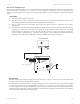
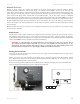
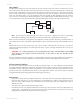
The Quick Release Fitting (1) is the entry point into the rear enclosure of the laser system. From there, the air lines
branch o into two paths: the optics protection path and the cone path. The optics protection path is a direct path
from the quick release tting (1) to the #2 mirror (4) and the #3 mirror (5). Since this is a direct path, the amount
of air pressure and ow that is coming from your compressed air source will be applied to the optics to help keep
them clean from ying debris. The cone/backsweep path goes through the ow adjustment valve (2) and then
to the cone (3). The amount of air owing through the cone is adjusted using the ow adjustment valve (2). The
cone path protects the focus lens and provides a downward ow directly into the beam path at the focus point.
5
1
2
3
4
or
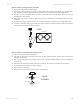
Note: Air will always be owing through the system as long as the compressed air source is turned ON.
We recommend installing a shut o valve in between your compressed air supply and the laser system.
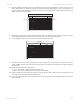
Before you run your material, we suggest that you adjust the air and/or gas ow. To do this, you must rst turn on
your compressed air source so that there is ow through the system. Now, either turn the laser system ON or leave it
OFF.
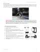
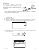
With the top door of the laser system open, pass a piece of paper underneath the cone and use it to note the
amount of air owing through the cone and against the paper or place your nger underneath the cone to try to
feel the pressure.
CAUTION: As a safety precaution, you should place your nger underneath the cone only
when power to the system has been turned OFF. If the power is ON, you should use the
paper method.
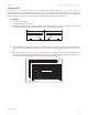
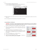
Turn the adjustment valve knob clockwise or counterclockwise until either the desired airow or PSI reading on
the gauge is achieved. Clockwise adjustments reduce ow while counterclockwise adjustments increase ow.
How it Works
Air Flow Setting Guidelines
Use as much or as little air ow necessary to produce the desired results. As a rule of thumb, start with low ow
and adjust upward until aming is suppressed. Setting the ow too high can result in excessive particulate matter
being blown around, causing faster system contamination. It can also push smoke back onto the material or into
the cut line and cause contamination of the surface or side edges of the material. The Air Assist option is intended
to suppress aming and/or melting of the material during laser processing.
Maintenance
Keep your air supply and/or gas supply moisture free. Check your desiccant (water dryer) frequently. Replace •
desiccant when saturated or use the manufacturer’s recommendation to remove water moisture from the
desiccant crystals. Water moisture may contaminate the Air Assist system and cause malfunction as well as
damage to the unit.
Clean your laser system as required when using Air Assist. •
Periodically check the cone alignment with the laser beam, especially if you have replaced or adjusted the laser •
systems optics. A misaligned cone will cause the beam to make contact with the inside of the cone, possibly
splitting the beam and/or reducing the power at the focus point.