
User guide

Link to Table of Contents
User Guide
104
VLS3.60, VLS4.60 and VLS6.60 Accessories
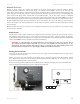
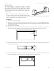
Manual Air Assist
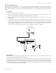
Manual Air Assist consists of a nozzle that attaches to the focus carriage, Optics protection adapters, tubing,
mounting brackets, needle valve and pressure gauge. The purpose of this system is to force air or other types of
gases directly onto the surface of your material to reduce the burning eects of the laser beam and help disperse the
smoke and gases created when cutting or engraving materials. The optics protection parts assist in helping keep the
optics cleaner from ying debris created from the pressurized nozzle. Use of this system requires a minimum
compressed air source capable of 60 PSI @ 2.5 cfm (4.1 bar @ 4.25 cubic meters/hour). This supply must be free of oil,
water and particulate matter. Another accessory called the “Air Assist Compressor” is available as a compressed air source.
Air Assist is not intended to decrease maintenance of the laser system. The use of Air Assist has been known to
increase the frequency of cleaning maintenance due to debris being blown around inside the engraving area during
laser processing.
Manual Air Assist does not have solenoids, is not computer controlled and can only deliver one air pressure per le.
It is also not gas compatible.
Requirements
The Air Assist option requires compressed air supplied from the Air Assist Compressor Unit (optional) or from a
user-supplied compressed air source. If you choose to provide your own source, it must be capable of supplying
50 PSI (pounds per square inch) (4.1 bar) at a constant rate of 2.5 CFM (cubic feet per minute) (4.25 cubic meters/hour).
The air supply must be oil-free, moisture-free and particulate ltered.
CAUTION: A contaminated air supply will cause severe damage to the laser system. Air or
gas supply pressures higher than 50 PSI (4.1 bar) can rupture the internal hoses of the
control box and can possibly damage the valves. Damage to the VersaLASER system from
contaminated or improper air or gas supply is not covered under warranty.
6
5
78
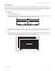
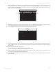
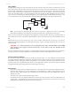
Making the Connections
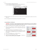
In the left rear part of the system you will nd the pressure gauge (1), ow adjustment valve (2), quick release
coupling (3) and release lever (4).
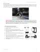
Push in the release lever and pull down on the quick release coupling to remove it from the machine. Attach
the compressed air supply hose to this tting (1/4 NPT threads) and use Teon tape on the threads to prevent
leaks. Re-insert the tting until it “clicks” into place.
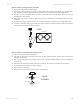
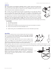
If you are not using the ULS Compressor, ULS recommends you congure your supply line (5) to a particulate lter
(6), desiccant/dryer (7) and then to an oil-free compressed air source (8).