
User guide

Link to Table of Contents
User Guide
102
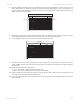
VLS3.60, VLS4.60 and VLS6.60 Accessories
1 2345678910 11 12 13 14 15 16 17 18 19 20 21 22 23
1
2
3
4
5
6
7
8
9
10
11
12
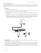
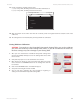
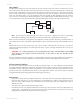
1) POSITION DIODE HERE 2) THEN HERE
3) AND FINALLY HERE
X-AXIS RULER
Y-AXIS RULER
Finally, position the red diode pointer at the:13.
(0 in, 18 in) (0 mm, 457 mm) position for the VLS4.60 and VLS6.60 ora.
(0 in, 12 in) (0 mm, 305 mm) position for the VLS3.60b. .
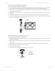
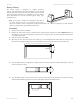
Align the bottom of the Y-Axis ruler with the red diode pointer and tighten down the bottom screw of the 14.
Y-Axis ruler.
The cutting table is now installed, but you must perform lens calibration.15.
Cutting Table Lens Calibration
CAUTION: To properly use the Downdraft Honeycomb Cutting Table, you need to calibrate
your focus lens to the top of the Cutting Table surface. If you do not calibrate the focus lens,
the focus carriage may cause damage to your Cutting Table.
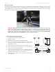
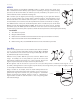
After you have installed the Downdraft Honeycomb Cutting Table 1.
into the VersaLASER, manually focus to the Cutting Table surface with
the Focus Tool.
Verify that the proper lens is selected from the Lens Size list.2.
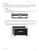
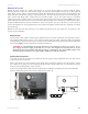
Once focused, go directly to your System Tab of the UCP and you will 3.
notice that the red CALIBRATE button for the Cutting Table box will
be activated.
Click on the CALIBRATE button. A window will appear.4.
Accept the new Z-height and click on SAVE.5.
You are now done calibrating the new Z-height for engraving or 6.
cutting on the Downdraft Honeycomb Cutting Table.