
User guide

Link to Table of Contents
User Guide
101
VLS3.60, VLS4.60 and VLS6.60 Accessories
1
23456789101112131415161718192021222324
1
2
3
4
5
6
7
8
9
10
11
12
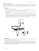
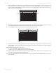
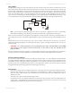
ADJUSTABLE MANIFOLD
EXHAUST PLENUM
SCREWSSCREWS
Slide the adjustable manifold squarely up against the exhaust plenum and tighten the four screws on the side 6.
of the cutting table. Be careful not to move the cutting table while tightening the screws. The objective is to
have the cutting table t snugly up against the rulers of the engraving table and the adjustable manifold t
tightly against the exhaust plenum.
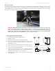
Now adjust the rulers of the cutting table so that they match the engraving eld of the laser system. Using the 7.
focus tool method, adjust the Z-Axis and focus directly onto the surface of the honeycomb.
Loosen slightly, but do not remove, the ve screws that hold down the rulers.8.
1
2345678910 11 12 13 14 15 16 17 18 19 20 21 22 23 24
1
2
3
4
5
6
7
8
9
10
11
12
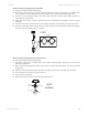
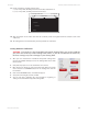
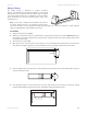
SCREWS
SCREWS
Activate the red diode pointer by opening the top door. Position the focus carriage at (0,0). With the red diode 9.
pointer still ON, slide the X-Axis ruler so that its zero point lines up with the red diode pointer. Tighten down the
left side screw.
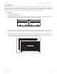
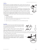
Now position the red diode pointer at the:10.
(32 in, 0 in) (813 mm, 0 mm) position for the VLS6.60 ora.
(24 in, 0 in) (610 mm, 0 mm) position for the VLS3.60 and VLS4.60.b.
Adjust the right side of the X-Axis ruler until it is lined up with the diode. Tighten down the right side screw of 11.
the X-Axis ruler. Now tighten down the middle screw.
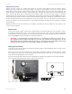
Line up the right edge of the Y-Axis ruler with the zero line of the X-Axis ruler and tighten down the top screw 12.
of the Y-Axis ruler.