
User guide
Link to Table of Contents
User Guide
73
User Manual
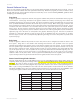
If using a color other than the exact colors listed above, the driver will attempt to match it to a color in the
driver that it most closely resembles. The driver will then use that color’s power setting and apply a halftone
pattern to represent the original color’s shade. For example, if using a color like pink to ll a rectangle, the driver
takes a reading of the percentage of dierent colors used to create that color and will use the power setting
assigned to one of the eight colors of the driver that it most closely resembles. It might be expected that the driver
will use the power setting assigned to the color red, but instead the driver may choose the magenta setting and
halftone the rectangle as a representation of the pink color’s lighter shade. To prevent the incorrect assignment of
laser power, be sure to use the correct colors. If using graphics with colors other than the eight listed above or to
simplify the assignment of power settings, try using the Clipart Mode feature in the driver. This feature will cause
the system to only use the power setting assigned to the color black and halftone all of the other colors.
Outlines and Fills
The driver distinguishes between raster mode (engraving) and vector mode (cutting) by the type of graphic artwork
being used. All graphics, other than outlines of very thin line widths will be interpreted as engraved images and
the raster mode will be used for output. If laser cutting is desired, set the line thickness of the lines that are drawn
in the graphics software to 0.001 inches (0.025 mm) or the smallest possible line thickness available. The printer
driver will interpret these objects as vectors and will cut them out providing that your software has the capability
of vector output. Basically, all software programs have the ability to provide raster output. However, not all
programs have the ability to provide vector output even if you set the line width to the smallest thickness
possible. Check page 61 of this guide for software that can vector output. The use of color lls or bitmaps will cause
the laser system to engrave. The combination of engraving and cutting is available in most graphics software. We
suggest that when combining engraving and cutting objects, use dierent colors for the lls and outlines since
engraving requires dierent power settings than cutting objects. One thing to keep in mind when creating cutting
objects is that if the outline thickness is set too thick, the driver might interpret the outline as a lled object and
will engrave the outline instead of vector. This might be desirable if engraving thick outlines is necessary. The
outline thickness at which the driver will interpret cut lines as lled objects is dependent on the software used.
Usually, any line thickness 0.008 inches (0.2 mm) or greater will engrave. The only way to determine the cross-over
point for line thickness is to experiment with dierent line widths. Software programs that do not have outline
capabilities denitely will not have the ability to cut.
Image Processing Order
When cutting or engraving a graphic image, the laser system will perform all engraving rst, and then proceed to
vector cutting. Raster engraving will proceed in the exact order of the colors listed in the driver. For example, all
black lled objects will engrave rst, then all red lled objects, then all green lled objects and so on. When all
engraved objects have been completed, the laser system will proceed to vector cut any outlines present in the
artwork. Vector output order is dependent on the “Soft” feature of the printer driver. Refer to the printer driver
controls for more details.
Overlapping Fills
If the artwork created has overlapping lled areas, the driver will automatically lter these lls to prevent the
overlapped area from being engraved twice. This is similar to color separation in the printing industry. The entire
lled area of the object on top will be engraved and only the visible part of the underlying lled area will be
engraved. The nal result is a what-you-see-is-what-you-get output. This way the color white can be used as an
eective drawing tool. Since the laser system will not engrave the color white (this is the background color), it can
be used to block out the undesired engraving areas of lled regions and/or bitmaps. However, you cannot use a
white ll to cover an outline, the outline will vector cut even though you cannot see it on screen.
Overlapping Outlines
The driver does not lter outlines that overlap each other. If you are placing one outline on top of another, both
outlines will be cut by the laser system. This is a useful feature that will allow deeper cutting by passing the laser
over a single outline path twice or more. To take advantage of this feature, duplicate the outline on top of itself.