User Guide www.ulsinc.
©2008 Universal Systems, Inc. All Rights Reserved. The Universal Laser Systems logo and name, and VersaLASER are registered trademarks, and High Power Density Focusing Optics, Quick Change, Rapid Reconfiguration, SuperSpeed are trademarks of Universal Laser Systems, Inc. All other company and product names are trademarks or registered trademarks of their respective companies. Universal’s laser systems are protected under one or more of U.S.
Thank you for choosing Universal Laser Systems®. We appreciate innovative customers like you who have made Universal Laser Systems an integral part of their business. Universal Laser Systems is committed to providing the highest level of customer satisfaction and support. To ensure your satisfaction, we urge you to read the documentation contained within the Reference Guide and User Guide CD.
Table of Contents USER GUIDE CD Chapter 1 - Laser System Specifications VersaLASER VLS2.30, VLS3.50…………………………………………………………………………………………………………………………7 VersaLASER VLS3.60, VLS4.60 and VLS6.60…………………………………………………………………………………………………………9 Professional Laser System PLS3.75, PLS4.75, PLS6.75 and PLS6.150D……………………………………………………………………………11 Industrial Laser System ILS9.75, ILS9.150D, ILS12.75 and ILS12.150D………………………….
Manual Air Assist……………………………………………………………………………………………………………………………104 Rotary Fixture…………………………………………………………………………………………………………………………………106 Professional Laser System PLS3.75, PLS4.75, PLS6.75 and PLS6.
User Guide Laser System Specifications Chapter 1 - Laser System Specifications Link to Table of Contents 6
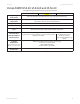
User Guide Laser System Specifications VersaLASER VLS3.60, VLS4.60 and VLS6.60 System Operating Environment Requirements (User Provided) VLS3.60 VLS4.60 VLS6.
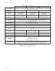
User Guide Laser System Specifications Model System Specifications VLS3.60 Laser Safety VLS4.60 VLS6.60 CO2 Laser, Interlocked Safety Enclosure = Class 1 Red Diode Pointer = Class 3R Work Area* 24 x 12 in (609.6 x 304.8 mm) 24 x 18 in (609.6 x 457.2 mm) 32 x 18 in (812.8 x 457.
User Guide Glossary of Terms Chapter 2 - Glossary of Terms Link to Table of Contents 15
User Guide Glossary of Terms #2 Mirror – A mirror located at the far left side of the X-Axis Arm (within the #2 mirror cover) used to direct the horizontal laser beam from the Beam Window into the Focus Carriage. #3 Mirror – A mirror (part of the focus lens assembly) (1) located in the Focus Carriage used to direct the horizontal laser beam downward onto the work piece.
User Guide Glossary of Terms Beam Window – An optic (1) mounted in the left hand rear of the enclosure through which the laser beam enters the enclosure. Belt – A toothed belt with high-strength, stretch-free Kevlar construction, driven by a motion system motor. Belts included: X belt for left-right movement of the lens carriage; two Y belts that move the Arm forward and backward; and a Z belt that moves the engraving table up and down.
User Guide Glossary of Terms Engraving Field – The horizontal work area (24” x 12” or 610 x 305mm) that is accessible by the laser beam for engraving and cutting – equal to the maximum “page” size for your laser system. Engraving area may vary based on speeds and thruput. Exhaust Port – Round spigot located on the back of the enclosure that allows connection of a fume extraction hose. Fill – A color, bitmap, fountain or pattern applied to the interior area of a vector graphic.
User Guide Glossary of Terms Fume Extraction (Exhaust) Blower – A radial-vane motorized blower that generates high vacuum to pull exhaust air through the enclosure. Must be properly installed and connected with ducting. Gear – A toothed pulley that is secured to the motor drive shaft. The gear drives a belt. Graphics Program – The software used to create bitmap and vector artwork executed by the laser system. CorelDRAW and Adobe Illustrator are examples of graphics programs.
User Guide Glossary of Terms Outline – The line that defines the shape of a vector graphic. In order for an outline to be recognized as a vector, it must be of minimum thickness – a “hairline” – less than 0.003 inches or 0.076 mm. PC – Personal Computer. The laser system requires a Windows-based operating systems as an integral part of its operation. Power Supply – An electrical component that converts wall-plug electricity into voltages required for electronics and CO2 laser operation.
User Guide Glossary of Terms Universal Control Panel (UCP) – The software supplied by Universal Laser Systems used to operate the laser system. This software program allows the user to view, store and execute jobs. Accessed by clicking the diamond-shaped Icon in the System Tray. USB 2.0 – Universal Serial Bus version 2.0 for high speed two-way communication. A standardized cable connection and communications protocol used to connect external devices (such as the laser system) to a computer.
User Guide Glossary of Terms Y-Axis – The front to back direction in the Main Enclosure. Also, the mechanical system used to move the X-Axis Arm front to back in the enclosure. Y-Axis Bearings – The bearings on the ends of the X-Axis Arm that guide it along the Y-rails. Y-Rails – The two parallel rails that guide the X-Arm front and back inside the Main Enclosure. Z-Axis – The up and down direction in the Main Enclosure.
User Guide User Manual Chapter 3 - User Manual Link to Table of Contents 23
User Guide User Manual LET’S GET STARTED! The User Guide is designed to provide you with information on how to operate your Universal laser system. The Users Guide section will walk you through System Operation, Accessories, and Basic Maintenance. Laser System Operation From the Universal Control Panel menus and buttons to the laser system keypad and basic printer driver features, this section describes many of the features of the laser system.
User Guide User Manual Viewer Tab System Controls • The green START button begins the engraving process. • Clicking the PAUSE button stops the engraving process and clicking the PAUSE button again resumes the engraving process where it was last stopped. • The four Navigation buttons move the focus carriage back and forth or left and right. • The two up and down buttons move the Z-Axis engraving table up or down. • The Home XY button re-homes/moves the focus carriage to the upper right hand corner.
User Guide User Manual Focus View (drop down list) The Focus View allows you to move the focus carriage to a desired position on the laser system table. • To have a full range of motion of the X-Axis arm, verify that you are zoomed out in the preview window by right-clicking on the mouse before entering the manual focus window. • Moving the cursor over the preview window once the focus button has been clicked changes your cursor to a blue target with dashed vertical and horizontal lines.
User Guide User Manual Relocate View (drop down list) The Relocate feature gives you the opportunity to move the image on the UCP into another area of the engraving field. This feature does not modify your original file’s image location. When this feature is activated, the image is surrounded by nine small white squares (anchor points) allowing you to move it around the basic view screen. The current anchor point selected, in blue, is the axis of movement.
User Guide User Manual File Management File Management displays the name of the current job, the number of jobs stored, the date and time the job was stored on your hard drive and the run time near the top of the window. Once the Print Cache reaches the maximum number of jobs, the printer driver deletes the oldest jobs as newest jobs enter the cache. • The print job navigation buttons allow you to preview the print jobs stored on your hard drive.
User Guide User Manual VLS2.30, VLS3.50, VLS3.60, VLS4.60 and VLS6.60 SYSTEM TAB The System Tab allows you to configure certain features of the laser system. Not all features will appear on the System Tab. • The PRINT CACHE number is adjustable. It indicates the maximum number of print jobs that you would like to be stored on your hard drive.
User Guide User Manual • If the laser machine was improperly shut down, the engraving table will home at start up. To have this feature turned off, check the ‘Disable Automatic Z-Homing.’ Disabling this feature can also be helpful when troubleshooting Z-Axis problems. • If you would like the laser system to re-home before it engraves a job, select ‘Home XY Before Engraving.’ • Universal laser systems contains an Air Pressure detection switch.
User Guide User Manual VLS3.60, VLS4.60 and VLS6.60 DIAGNOSTICS TAB The Diagnostics Tab displays important information about your laser system and personal computer. This information can be used for troubleshooting purposes. • ENGRAVER shows the current Firmware and FPGA version being used. It also displays the Serial Number of your laser system. The Serial Number is needed when calling the Customer Service Department at ULS.
User Guide User Manual Materials Database Printer Driver This tab of the printer driver is for the beginning user and automatically calculates the appropriate power and speed settings according the material selected. Category List This section allows you to choose from eight original types of material categories. Material List Once you select a category, a variety of material types will appear to the right of the category section.
User Guide User Manual Material Code The Material Code box will automatically display a new material code number when making a new material and category. You can add a custom Material Code from 9000-9999 if desired. Taper This drop down menu is activated when Print Mode is set to Rubber Stamp. This feature is similar to the one in the Raster sub-tab for Rubber Stamping. 3D Power This button can be activated by setting the Print Mode to 3D.
User Guide User Manual How to create a new Category and Material 1. Select one of the existing Categories on the left and click on the NEW button. 2. From the Category drop down menu list on the left, select ‘**New Category.’ 3. The Material Category window appears allowing you to type a name of the new category in the blank space. A Category ID (900-999) will automatically be assigned once a new category is made. 4. Click the OK button. 5.
User Guide User Manual The VersaLASER Keypad The Keypad on the laser system provides limited access to controls necessary for cutting and engraving operations. When the laser system has finished initializing and homing, and if all the doors are closed, the red light on the keypad will be illuminated and ready to run a file. The Green or Red LED (Light Emitting Diode) will display differently depending on the current state of the laser system. Please refer to the chart below.
User Guide User Manual Advanced Laser System Operation From the PPI and speed settings to Rubber Stamp and Image Enhancement settings, this section covers how each feature of the Manual Control Printer Driver funtions for the advanced user. Note: When adjusting the printer driver settings in the Manual Control Tab, it is highly recommended that you practice engraving or cutting on a scrap portion of that material in case the settings need to be re-adjusted to obtain the desired results.
User Guide User Manual PPI Available settings are 1 to 1000. The laser beam is always pulsing and never “on” continuously even though it may appear that way. The PPI setting indicates how many laser pulses, per linear inch, the laser cartridge will emit. The pulsing of the laser beam is electronically linked to the motion system. These pulses will always fire, equally spaced, from one to the next, regardless of changes in speed.
User Guide User Manual Flow (Computer Controlled Air Assist only) This feature will not appear if you do not have the Computer Controlled Air Assist option. If you do have Computer Controlled Air Assist, but are not using it, you MUST leave the setting to OFF, otherwise your system will hesitate up to 10 seconds after you press the start button on the machine.
User Guide User Manual Raster Sub-Tab Print Special Effects In this dropdown list, you can choose from four different printing modes, Normal (default), Clip art, 3D and Rubber Stamp. Clip Art This control simulates laser printer output and is very useful if using a drawing with many colors, shades of gray or many outlines. It is recommended to turn this control ON when using DRAWN clip art because there may be some underlying cutting lines hiding behind filled areas.
User Guide User Manual This is what we call the “nominal” power setting. Over-powering the material will produce poor results. In your graphics software, create a series of five rectangles that are about ¼ inch high and 6 inches wide as in the following diagram: Starting with the top rectangle, set the power setting to a value that you know will be too low.
User Guide User Manual Setup Button When you click this button, the ULS 3D Power Calibration screen will appear. Notice that there are 16 slider bars representing the 16 shades of gray of the calibration scale. The 00 and the 15 are not adjustable as they represent white and black. The other 14 can be adjusted.
User Guide User Manual Image Options Invert Page This converts all black objects into white and all white objects into black for the entire page. This is very useful for engraving a full sheet of rubber stamps. CAUTION: When using the “Invert Page” feature you reduce your page size so that the entire work area is not engraved. may need to Mirror Page This mirrors the entire page from left to right (horizontally). It will not mirror individual objects or selections.
User Guide User Manual Image Density (DPI) settings will also have an effect on vector quality and vector speeds when vectoring lines other than straight horizontal or vertical lines. For example, a circle is made up of very small straight-line segments linked together at very small angles. If you choose a high quality setting such as 6 (1000 DPI), then these segments are as small as possible and they are high in quality.
User Guide User Manual Black and White Mode The Black and White mode thresholds the image at 50% black. Each pixel that is greater than 50% black will be converted into white and each pixel that is 50% black or less will be converted into black. This effect is very similar to trying to duplicate a photograph using a photocopier. Helpful Tip Engraving grayscale bitmaps using a dithering pattern requires some practice and a bit of trial and error to achieve perfection.
User Guide User Manual DEFINITION: Definition adjusts the difference between low density and the high density part of the graphic. The low density parts of the graphic are typically the ascenders and descenders of text, single pixels that may be horizontally spaced far from other pixels or the start of the graphic in the direction of the raster stroke. Refer to the following diagram: Universal Laser Systems, Inc.
User Guide User Manual Step 2: Using text to set the CONTRAST parameter. Type in a random line of text, using the Times New Roman font, set at 8 or 10 points in size. Make sure that the text string is at least 6 inches long and that the string includes punctuation marks, spaces and lower and upper case letters as in the following example: Universal Laser Systems, Inc.
User Guide User Manual this procedure for all your materials and save your parameters. This may sound like a big job, but the additional productivity and engraving quality that your system is capable of producing is well worth the small amount of time spent. Vector Sub-Tab Vector Optimizer The four available selections apply to vector output only and have no effect on raster images.
User Guide User Manual CAUTION: Do not attempt to use the vector-scaling feature when your graphic extends out to the absolute edge of the engraving field. You may accidentally cause the driver to attempt to print past the edge of the maximum allowable page size. Unexpected results may occur. If you use this feature, the actual allowable page size decreases by the same amount that you are attempting to offset. Engraving Field Sub-Tab Units Units allows you to change between Metric and Inches.
User Guide User Manual Third-Party Graphic Software Configuration Choosing the right graphics software program to run the laser system is essential for maximum usage and control of the laser system. Not all software can be used to run the laser system because many have limitations. Setting up your software correctly is essential to running the laser system properly. The following examples assume that you are configuring the software for a VersaLASER system.
User Guide User Manual Adobe Illustrator CS or CS2 Note: Adobe Illustrator CS or CS2, in combination with the new ULS printer driver version 5.24.38 or later, is now capable of both raster and vector output as well as full-field engraving capability. The following procedure assumes that you are familiar with the use and operation of Windows XP and Adobe Illustrator CS or CS2. 1. Close all Windows programs. 2. Upgrade to Adobe Illustrator CS, but do not launch it yet. 3.
User Guide User Manual Adobe Illustrator CS3 Part 1: Setting the Default Workspace 1. Start Illustrator CS3 from your Windows XP/Vista compatible PC. • Illustrator CS3 Preferences box will open. 2. Select FILE CREATE NEW BASIC RGB DOCUMENT. • The new document options box will open. Make the following settings: a. Set Units to inches. b. Set the Height and Width to match the size of your laser system’s work table. c. Set the Color Mode to RGB. d. Click “OK”. Part 2: Setting the Stroke 1.
User Guide User Manual Part 3: Editing the Swatch Palette 1. Open your Swatch Palette as follows: • Main Menu Window Swatches Left Click “OK” • Delete all swatches that are not basic RGB or gray scale by left clicking to select them and then clicking the “Delete Swatch” garbage can icon is the lower right-hand corner of the swatch box. Keep RGB BLACK, RED, GREEN, BLUE, YELLOW, MAGENTA, CYAN.
User Guide User Manual AutoCAD 2000i, 2002 and 2004 Note: AutoCAD version 2000 is not compatible with ULS laser systems. You must upgrade to version 2000i or higher. Also, we recommend installing ULS printer driver version 5.24.38 or higher. 1. Make sure the ULS Printer driver is installed prior to setting up AutoCAD. 2. If AutoCAD is already installed and you are simply upgrading ULS printer drivers: • Close all open programs. • In Windows, Click Start>Printers & Faxes.
User Guide User Manual AutoCAD LT 2007 & 2008 Note: These instructions are for plotting from “Model Space.” Also, we recommend installing ULS printer driver version 5.24.38 or higher. 1. SET DRAWING LIMITS a. From the Main Menu select FORMAT DRAWING LIMITS This will allow you to enter the model space limits of your Universal laser system work table size. For example, if your work table size is 32”x18” (813 x 457 mm), you would set the following drawing limits: i.
User Guide User Manual 3. ADD NEW PLOTTER a. Select FILE PLOTTER MANAGER b. Select ADD-A-PLOTTER WIZARD and click NEXT. c. Select System Printer and click NEXT. d. Select your Universal Laser System (i.e. VLS6.60) and click NEXT. e. Click the Edit Plotter Configuration button and select Modify Standard Paper Size (Printable Area). f. Select User-Defined LANDSCAPE (Modify) and change the margin values to zero. Top = 0.0 Bottom = 0.0 Left = 0.0 Right = 0.0 g. Click NEXT YOUR SYSTEM (i.e. VLS6.60) h.
User Guide User Manual CorelDRAW X3 or X4 Note: CorelDRAW X3 or X4 is compatible with Windows XP and Windows Vista. We also suggest not running it with Windows 95/98. Therefore, we have only included setup instructions for Windows XP and Windows Vista. 1. Make sure that you have installed all Service Packs and software patches from Microsoft. Please contact Microsoft if you have any questions regarding these upgrades. ULS is not responsible for any problems as a result from the usage of these patches. 2.
User Guide User Manual 10. While still in the “Options” dialog box, double-click on “Global” to expand the list. Double-click on “Printing” to expand the list. Now click on “Driver Compatibility.” Make sure that the laser system name is displayed in the printer drop-down list. In the “Settings specific for this driver” dialog box, make sure that ALL the check boxes are UNCHECKED. Now click on “OK” to close the “Options” dialog box. 11.
User Guide User Manual Graphic Page Configuration for Rotary (CorelDRAW) Note: If you are using the Material Database printer driver to engrave on an object, you do not need to change the page size of your graphic software. If you are using the Manual Control printer driver, please follow the steps below. 1. With your graphics software open, proceed immediately to “Printer” setup “Properties” button. and then click on the 2.
User Guide User Manual 4. Activate the Rotary feature on the printer drive, by clicking on “Enable” box. Type the diameter of the object under “Diameter.” 5. Notice that while typing the diameter, the height dimension changes automatically. Remember or write down this new dimension. 6. Click on “OK” on the printer driver and go back to the graphic software page setup and change the height to EXACTLY match the dimension that was calculated in the previous step. 7.
User Guide User Manual General Software Set-up There are many software programs that you can purchase off-the-shelf that will work with the laser system. Some of them can access more features of the laser system than others may. Whichever program you choose, it must be set up to work with the laser system, otherwise unexpected results may occur. Use the following GENERAL guidelines when configuring your software program.
User Guide User Manual If using a color other than the exact colors listed above, the driver will attempt to match it to a color in the driver that it most closely resembles. The driver will then use that color’s power setting and apply a halftone pattern to represent the original color’s shade.
User Guide User Manual Hidden Vector Lines in Artwork The driver does not automatically filter out outlines that are overlapped by engraved objects such as fills. If there are filled objects with some hidden outlines underneath, the laser system will engrave the fill and cut the hidden outline on top of the fill. This is a common occurrence when using pre-drawn clipart designed for laser printers. To prevent this from happening, turn on the Clipart Mode feature in the driver.
User Guide User Manual you may want to experiment by using your bitmap image-processing program to make the conversion. These software programs usually have more options for controlling the size, angle, shape and the amount of black and white dots (pixels) created when converting the image. Experiment with all of the controls to see which looks the best. Big dots look good on some materials and small dots look better on others.
User Guide Accessories - Installing and Operating Chapter 4 - Accessories - Installing and Operating Link to Table of Contents 76
User Guide VLS3.60, VLS4.60 and VLS6.60 Accessories VersaLASER VLS3.60, VLS4.60 and VLS6.60 There are optional accessories, not included with the basic laser system, that are available at additional cost. Instructions on how to use these accessories are included in this section. The user can purchase and install all accessories, except Air Assist, which is a factory installed option only. CAUTION: Before attempting to use any accessory, make sure that you have read the entire manual up to this point.
User Guide VLS3.60, VLS4.60 and VLS6.60 Accessories 3. Use a thumbscrew (1) to hold the Back Sweep in place. Adjust the Back Sweep’s height by loosening the thumbscrew (2) and adjusting it up or down. Tighten the thumbcrew once it is at the correct height. To adjust the angle of the air flow, turn the screw (3) in small increments to direct the air to the desired position over the material.
User Guide VLS3.60, VLS4.60 and VLS6.60 Accessories Air Assist Compressor The Air Assist Compressor option is a 60 PSI @ 2.5 cfm (4.1 bar @ 4.25 cubic meters/hour) source for oil-free, water-free and particulate free compressed air. It contains a sound insulated air compressor, water dryer (desiccant) and coalescent particulate filter. This compact and custom designed unit is a great complement to the Air Assist System option. Installation 1. Make sure the laser system is turned off. 2.
User Guide VLS3.60, VLS4.60 and VLS6.60 Accessories Removal, Cleaning and Replacement of the Filter 1. Turn the Air Compressor OFF and unplug it. 2. Unscrew the cover by turning it 1/8 turn counterclockwise like you were unscrewing a jar, and pull down. The clear plastic container might still remain attached to the top. Gently pull this part straight down. 3. You will see a red colored foam filter. Unscrew the filter and wash it out with water. Make sure that it is completely dry, then reinstall. 4.
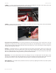
User Guide VLS3.60, VLS4.60 and VLS6.60 Accessories Air Assist Cone To install the cone, insert the cone (1) into the cone base completely until it bottoms out. Tighten the setscrew on the side of the cone base (2) until it is snug. To remove the cone, simply loosen the setscrew (2) and pull the cone straight down. Do not remove or loosen the cone base mounting screws (3) & (4) to mount or dismount the cone. These screws keep the cone base aligned with the laser beam.
User Guide VLS3.60, VLS4.60 and VLS6.60 Accessories Cutting Table The purpose of the Cutting Table is to support the material that you are cutting above the engraving table’s surface to minimize surface contact area. It also redirects exhaust airflow below and above the material for efficient smoke removal. The cutting table is installed directly on top of the engraving table. The cutting table material is reflective only in the area that contacts your material to minimize laser beam reflection.
User Guide VLS3.60, VLS4.60 and VLS6.60 Accessories 6. Slide the adjustable manifold squarely up against the exhaust plenum and tighten the four screws on the side of the cutting table. Be careful not to move the cutting table while tightening the screws. The objective is to have the cutting table fit snugly up against the rulers of the engraving table and the adjustable manifold fit tightly against the exhaust plenum.
User Guide VLS3.60, VLS4.60 and VLS6.60 Accessories 13. Finally, position the red diode pointer at the: a. (0 in, 18 in) (0 mm, 457 mm) position for the VLS4.60 and VLS6.60 or b. (0 in, 12 in) (0 mm, 305 mm) position for the VLS3.60. 1) POSITION DIODE HERE 2) THEN HERE X-AXIS RULER 1 2 3 4 5 6 7 8 9 10 11 12 13 14 15 16 17 18 19 20 21 22 23 1 2 Y-AXIS RULER 3 4 5 6 7 8 9 10 11 12 3) AND FINALLY HERE 14.
User Guide VLS3.60, VLS4.60 and VLS6.60 Accessories HPDFO High Power Density Focusing Optics (HPDFO) produces a smaller, focused laser beam “spot” than a standard laser beam delivery optical system. Depending on the type of material being processed, and the desired effect, the effective spot size produced by this option can be as small as 1/4th the size of a standard 2.0 focusing lens.
User Guide VLS3.60, VLS4.60 and VLS6.60 Accessories Manual Air Assist Manual Air Assist consists of a nozzle that attaches to the focus carriage, Optics protection adapters, tubing, mounting brackets, needle valve and pressure gauge. The purpose of this system is to force air or other types of gases directly onto the surface of your material to reduce the burning effects of the laser beam and help disperse the smoke and gases created when cutting or engraving materials.
User Guide VLS3.60, VLS4.60 and VLS6.60 Accessories How it Works The Quick Release Fitting (1) is the entry point into the rear enclosure of the laser system. From there, the air lines branch off into two paths: the optics protection path and the cone path. The optics protection path is a direct path from the quick release fitting (1) to the #2 mirror (4) and the #3 mirror (5).
User Guide VLS3.60, VLS4.60 and VLS6.60 Accessories Rotary Fixture The Rotary Fixture is designed to engrave cylindrical objects. Two attachments come with the fixture: a cone shaped disk attached to the motorized end of the fixture and an inverted cone shaped disk attached to the adjustable end of the fixture. These attachments are used to hold wine glasses, mugs, cups, baseball bats, etc.
User Guide VLS3.60, VLS4.60 and VLS6.60 Accessories 7. With the power to the system still OFF, connect the 7-pin Rotary Fixture control cable to the receptacle on the laser system (6). 1 2 3 4 5 6 7 8 9 10 11 12 13 14 15 16 17 18 19 20 21 22 23 24 1 2 3 4 5 6 7 8 9 10 11 12 6 Loading Material 1. Before loading the glass into the fixture, measure the diameter (1) of the glass in the area where the engraving is to be located by using a caliper or similar measuring device.
User Guide VLS3.60, VLS4.60 and VLS6.60 Accessories 3. Power ON the laser system. The rotary will run through a self test and will slightly rotate. This movement is normal. If you are using the rotary for the first time or replaced the laser system’s CPU, rotary calibration is needed, so proceed to the next step. If rotary calibration is not needed proceed to the next page and see “Determining Graphic Placement.” Rotary Calibration 1.
User Guide VLS3.60, VLS4.60 and VLS6.60 Accessories 5. Use the Focus Tool to focus on top of the flat surface of the concave metal fixture with the focus tool. Do not focus on top of the black metal cover that is located on the left hand side of the rotary. 6. After focusing is complete, click both SAVE buttons on the Rotary Calibration window. If asked to overwrite an existing position, accept the new value by clicking on YES. 7.
User Guide VLS3.60, VLS4.60 and VLS6.60 Accessories Printer Driver Settings 1. With your graphics software open, proceed immediately to “Printer Setup” and open the printer driver. 2. In the printer driver, click on the Engraving Field sub-tab within the Manual Control Tab. 3. Click on the “Max Size” button. 4. Then click on the “Enable” selection box in the Rotary section. 5. Type in the diameter of the glass that was measured. 6.
User Guide Maintenance Chapter 5 - Basic Maintenance Link to Table of Contents 169
User Guide Maintenance VersaLASER VLS3.60, VLS4.60 and VLS6.60 Keeping the laser system clean will ensure the highest quality engraving. A clean laser system is the best performing laser system. The frequency of cleaning will depend on the type of material being engraved, your exhaust system, the operating environment and the amount of laser system usage over a given period of time.
User Guide Maintenance Cleaning and Maintenance Supplies • Mild soap solution mixture of 1 tablespoon (14.
User Guide Maintenance Optics A visual inspection of the #2 and #3 mirrors, beam window and focus lens should be performed at least once a day. CAUTION: Do not clean an optic that is visually clean. Excessive cleaning can damage the optic. To prevent contamination, wash your hands thoroughly before cleaning any optic. Never touch any optic with your fingers. The acids from your skin can destroy the optical coatings.
User Guide Maintenance 3. Tilt the front cover enough to enable you to apply the lens cleaning solution directly to the #3 mirror and to the focus lens. 4. Flood the reflective surface of the #3 mirror with the solution. If heavy debris is present, let the solution soak in for a minute. 5. Roll a fresh cotton swab across the mirror in one direction. Use a fresh swab for each pass. Be gentle when cleaning the optic to avoid scratching the surface.
User Guide Maintenance Exhaust Plenum 1. Power on the laser system and UCP. 2. Using the Z-Axis buttons on the laser system or UCP, raise the Z-Axis table as high as possible. 3. Power the system OFF. 4. Open the front door. 5. Locate and remove the two socket head cap screws found on the inside of the laser system. 6. Using both hands, reach in and grasp the exhaust plenum. 7. Lift the plenum straight up until the tabs (1) of the plenum clear the two flat head screws (2) on which they are resting.
User Guide Maintenance Cooling Fan Filters This air-cooled laser system will require periodic cleaning of the cooling fan filters. Since ambient air is used to cool the laser cartridge, the air must be filtered before it enters the inside of the laser system. Dirt or dust contamination may reduce the cooling fan’s ability to keep the laser cartridge, as well as the CPU and power supply, from overheating.
User Guide Maintenance Maintenance Schedule Since the maintenance requirements of the laser system are dependent on the type of material being run, the quantity of material being removed, the hours of operation and the quality of the exhaust blower, you should define your own schedule.
User Guide ULS Reference Guide Book Chapter 6 - ULS Reference Guide Books Link to Table of Contents 198
User Guide ULS Reference Guide Book Installation & Set-up Guide: VersaLASER VLS3.60, VLS4.60 and VLS6.
User Guide ULS Reference Guide Book The Installation & Set-up Guide is designed to provide you with step-by-step instructions for proper installation and set-up of your Universal laser system. Before getting started, you should become familiar with each section of the Installation & Set-Up Guide: Proper Operating Environment Procedures, Software Installation and Requirements, Assembling Your System and Running Your First Job.
User Guide ULS Reference Guide Book Electrical Power Source (User Supplied) 1. For your system’s electrical requirements, please refer to the “INPUT POWER” label near the power inlet. 2. CAUTION: Never remove the ground lead to the electrical cord and plug the VLS system into a non-grounded outlet. A laser system that is not properly grounded is hazardous and has the potential to cause severe or fatal electrical shock.
User Guide ULS Reference Guide Book Note: The following diagram shows a typical exhaust system layout. Use this as a guideline for proper exhaust system installation. Although this diagram serves as an example, we recommend you consult with a licensed contractor to meet local safety and building code requirements and to also calculate the correct size blower required for your particular installation.
User Guide ULS Reference Guide Book Software Installation and Requirements Your computer is a critical component in the operation of the VLS system. In fact, you cannot operate the VLS system if your computer is not connected, powered on, running Windows and running the Universal Control Panel (UCP) software. You can only run one VLS system per computer at a time. You will need to have a separate computer for each VLS system you own. The VLS system is not designed to be a network printer.
User Guide ULS Reference Guide Book Optimizing Windows XP Performance Windows XP, by default, displays many “visual effects” that slow down the computer. We recommend that you turn off these effects by right-clicking on the “My Computer” icon on your desktop, then click “Properties” and then click the “Advanced” tab. In the Performance section, click “Settings,” then click “Adjust For Best Performance” and then click “Apply.
User Guide ULS Reference Guide Book Universal Control Panel (UCP) Installation CD-ROM At this point you need to install the Windows XP/Vista Universal Control Panel (UCP) and printer driver. In order to install the software, you need to have administrative privileges on the computer before starting installation. The Software Installation CD-ROM can be found on the inside of this manual reference guide. 1. Insert the Software Installation CD-ROM into your PC’s CD drive.
User Guide ULS Reference Guide Book 4. The installation process will proceed as indicated by a progress bar. Be patient. Loading the files can take a few minutes depending on your computer’s processor speed. 5. When the installation process is finished, the “Completing the ULS Software Setup Wizard” window will appear. Read the instructions and make your desired selection. If you Reboot Now, save all your work prior to rebooting.
User Guide ULS Reference Guide Book Assembling Your VersaLASER System Familiarize yourself with the instructions before getting started. Depending on which model VersaLASER system you have purchased, assembly of your laser system may be required. Once the system has been assembled, it is necessary to install the laser cartridge on the back of the machine and perform a beam alignment check. Do not power up your laser system until the final step, “Checking Beam Alignment.
User Guide ULS Reference Guide Book 4. With the assistance of three or four other people, place the system on top of the cart and loosely install the provided screws that attach the machine to the cart. Be careful not to pinch your fingers. 5. Open front door all the way to ensure that it does not come in contact with the cart legs. If the door should come in contact with the cart legs, gently pull the cart legs apart to ensure there is non-contact between the door and the cart legs.
User Guide ULS Reference Guide Book System Assembly - VersaLASER VLS6.60 System 1. Unpack the laser system from its packaging. 2. Place the laser system in the desired location for operation. a. If a doorway is not wide enough to pass the laser system through, the system can be detached from the cart stand and carried through the door on it’s side. b.
User Guide ULS Reference Guide Book Laser Cartridge Installation 1. Make sure that your power cord to the system is not plugged in at this time. Place your finger in the slotted hole and gently pull back on both sliding latches. Gently fold back the rear cover. Note: some laser systems are shipped with keyed locks. Note: Access latches for the laser cover are lockable. However, all systems are shipped from the factory with latches unlocked.
User Guide ULS Reference Guide Book 3. Observe the “V” groove along the upper (3) and lower (2) part of the laser cartridge base plate and the alignment plate (1) at the end of the base plate. 4. Pick up the laser cartridge by the ends and tilt it at a 30 degree angle as shown (1). Mount the cartridge onto the mounting blocks shown in step 2 (page 229) by placing the upper “V” groove on top of the mounting blocks.
User Guide ULS Reference Guide Book 5. Slowly rotate the laser cartridge, making sure that the alignment plate is centered in the gap in the alignment fork. As you slowly release the weight of the laser, you should feel it lock itself smoothly into place. Never force the laser into position. If the laser does not install smoothly, check for obstructions such as pinched wires or hoses or a binding laser latch. Once installed, verify that the alignment plate is centered within the alignment fork. 6.
User Guide ULS Reference Guide Book Laser System Leveling 1. Place a bubble level (1) across the front (2) and rear cart legs (3). Adjust the caster height using the adjustment screw (4) until both the rear part and the front part of the cart legs are level with respect to each other. Once the system is level, secure all casters by tightening the nut (5) up against the cart leg. 2. Open the top door and remove the rubber band that is securing the arm in place. 3.
User Guide ULS Reference Guide Book 5. Place the focus tool* against the black lens plate (focus carriage) so that the flat edge of the focus tool rests against the front side of the focus carriage as illustrated. Take note of the fit of the focus tool (it should look like the diagram to the right) in the upper left corner of the system. This corner will be your reference point. *Alternate leveling method available. See page 234. 6.
User Guide ULS Reference Guide Book 7. If one or more of the other corners does not match the upper left corner, adjust the caster directly underneath that corner up or down until the focus tool fit at that corner matches the fit at the upper left corner. First loosen the lock nut (1), then turn the adjusting screw (2) in 1/8 turns. Once the foot is at the correct height, tighten the lock nut (1). When you are done the focus tool fit at all four corners should be the same. 1 2 8.
User Guide ULS Reference Guide Book Finalizing the Connections Make the following connections in the order described, otherwise static electricity can potentially damage the computer and/or the laser systems electronics. 1. Connect the 3-inch (76.5 mm) flexible rubber exhaust system to the rear of the laser system if you have not already done so. 2. Connect the laser system’s power cord and your computer’s power cord to a grounded electrical outlet. 3. Do not power on the laser system at this time.
User Guide ULS Reference Guide Book 5. USB 2.0 Hi-Speed (Only) The laser system comes equipped with a high quality, 6-foot (1.82 meters) USB 2.0 certified cable. We recommend you use this provided cable. CAUTION: Do not use any adapters, extension cables, USB cable longer than 6 feet (1.82 meters), or other devices between the computer’s USB port and the port on the laser system, or sporadic or unpredictable behavior may result. a.
User Guide ULS Reference Guide Book c. Select “Install the software automatically.” Then Click “Next” to continue. You do not need to insert the Software Installation CD-ROM. d. A warning message will appear. Select “Continue Anyway.” Do not be concerned. Installing the ULS Firmware will not harm your computer in any way. The firmware will begin to load. e. Click “Finish” to close the Wizard. f. Another set of New Hardware Wizard windows may appear after the initial USB connection.
User Guide ULS Reference Guide Book Checking Beam Alignment Note: You will not engrave anything at this time. 1. Open the top door. 2. Place a small piece of masking tape across the 3/4” (19 mm) hole in the focus carriage (1). Gently rub the tape around the edge of the hole so that you can see the outline of the hole through the tape (2) . 3. Power on your computer and verify that the Universal Control Panel (UCP) icon is present on the taskbar.
User Guide ULS Reference Guide Book Running Your First Job We will now illustrate how to use your laser system to engrave on a piece of anodized aluminum from start to finish. In this example, you will raster engrave a Test Card on a 2 x 3.5 inch (50.8 x 89 mm), 0.0195 inch (0.49 mm) thick piece of anodized aluminum. Note: For this example we will be using CorelDRAW X3 and the CorelDRAW sample file provided on the software CD. Install CorelDRAW, but do not start a new project.
User Guide ULS Reference Guide Book Step 3 – Printing to your VersaLASER System (Materials Database Tab) You are using the Materials Database Tab in the printer driver. Other graphic software programs may differ. 1. Verify that the UCP is running in the taskbar. 2. When you are ready to print the job, click FILE and then click PRINT.
User Guide ULS Reference Guide Book Step 4 – Starting the Process 1. Turn on the exhaust and VersaLASER system. Note: Laser system cooling fans are variable speed and may speed up and slow down during operation as needed to cool the lasers. 2. Make sure the material is positioned correctly within the engraving area. 3. Close the top door. 4. Click the green START button on the UCP to begin laser processing (Figure 6 on previous page). CAUTION: Observe that the laser system is functioning as desired.
User Guide ULS Reference Guide Book ULS Safety Guide Link to Table of Contents 291
User Guide ULS Reference Guide Book Safety Description of Appropriate Use This device is designed for laser cutting and engraving in an office, laboratory, workshop or light duty manufacturing environment. Materials to be processed must fit completely inside the system for proper operation.
User Guide ULS Reference Guide Book DANGEROUS VOLTAGES ARE PRESENT WITHIN THE ELECTRONICS ENCLOSURES OF THIS SYSTEM. Access to these areas is not necessary during normal operation. If it becomes necessary to open one of these enclosures for service reasons, please remember to disconnect the power cord from your electrical supply. NEVER REMOVE THE GROUND LEAD TO THE ELECTRICAL CORD AND PLUG THE SYSTEM INTO A NON-GROUNDED OUTLET.
User Guide ULS Reference Guide Book Laser Safety When Using the Optional Class 4 Module (ILS Only) The Industrial Laser Series (ILS) laser system is equipped with interlocked access doors on either side of the unit. An optional device is available to allow the user to operate the laser system with the side doors open. This device bypasses the safety interlocks on the side doors of the ILS laser system.
User Guide ULS Reference Guide Book any protective equipment such as specially designed eyewear, protective equipment and clothing needed when operating, maintaining or servicing a Class 4 laser system. Further, the Owner will ensure that no juveniles operate the laser, and that mirrors, lenses and other reflecting materials are fixed and are only moved in a controlled manner if the last is in use. E. The LSO will be responsible for auditing all safety measures on a regular basis.
User Guide ULS Reference Guide Book Safety Labels CDRH and CE regulations require that all laser manufacturers affix warning labels in specific locations throughout the equipment. The following warning labels are placed on the laser system for your safety. Do not remove these labels for any reason. If the labels become damaged or have been removed for any reason, do not operate the laser system and immediately contact Universal Laser Systems, Inc.
User Guide ULS Reference Guide Book VLS3.60, VLS4.60 and VLS6.60 CAUTION LASER RADIATION DO NOT STARE INTO BEAM OR VIEW DIRECTLY WITH OPTICAL INSTRUMENTS CLASS 3R LASER PRODUCT LASER DIODE WAVELENGTH: 630-680 nm MAX.
User Guide ULS Reference Guide Book WARNING TO AVOID RISK OF ELECTRIC SHOCK ALWAYS DISCONNECT POWER CORD BEFORE REMOVING THIS COVER 221-0020-0 221-0021-0 (Main grounding point) CAUTION CLASS 4 INVISIBLE LASER RADIATION WHEN OPEN AND INTERLOCK FAILED OR DEFEATED AVOID EYE OR SKIN EXPOSURE TO DIRECT OR SCATTERED RADIATION 221-0016-0 WARNING THIS SYSTEM IS DESIGNED FOR USE WITH INERT AND NON-OXIDIZING GASES ONLY (i.e. DRY CLEAN AIR, CARBON DIOXIDE, HELIUM, NITROGEN).
User Guide ULS Reference Guide Book CAUTION WARNING CLASS 4 INVISIBLE LASER RADIATION WHEN OPEN AND INTERLOCK FAILED OR DEFEATED AVOID EYE OR SKIN EXPOSURE TO DIRECT OR SCATTERED RADIATION TO AVOID RISK OF ELECTRIC SHOCK ALWAYS DISCONNECT POWER CORD BEFORE REMOVING THIS COVER 221-0016-0 221-0020-0 ! WARNING Do NOT use in medical or surgical applications or to manufacture medical devices.
User Guide ULS Reference Guide Book EU Declaration of Conformity Product Identification: VLS2.30, VLS 3.50, VLS3.60, VLS4.60, VLS6.60, PLS3.75, PLS4.75, PLS6.75, PLS6.150D, ILS9.75, ILS9.150D, ILS12.75 and ILS12.150D Laser Engraving and Cutting Systems Manufacturer: Universal Laser Systems, Inc. 16008 N. 81st St.
User Guide ULS Reference Guide Book FCC Compliance This ULS laser system has been tested and found to comply with Federal Communication Commission (FCC) directives regarding Electromagnetic Compatibility (EMC). In accordance with these directives, ULS is required to provide the following information to its customers. FCC Compliance Statement and Warnings This device complied with FCC Rules Part 15. Operation is subject to the following two conditions: 1.
www.ulsinc.