
Troubleshooting guide


INSTALLATION
Section 2-2
Exhaust System (user supplied)
• The exhaust system MUST be capable of supplying a minimum of 500 CFM (cubic feet per minute) of
airflow while under a load of 6 inches of static pressure (850m3/hr at 1.5kPa). DO NOT install
forward incline, backward incline, in-line, or ventilator fans because these types of air handlers are
inadequate and inappropriate for this type of installation. A high-pressure blower MUST be used to
meet minimum airflow requirements.
• The blower MUST be mounted on the OUTSIDE of the building.
• Rigid tubing should be used for 90% of the distance traveled between the blower and the laser
system. The tubing should be smooth walled and have as few 90 degree bends as possible.
• Install a gate to control airflow and to close off the exhaust from the outside environment when the
laser is not in use. Place this gate within 5 – 10 feet from the laser system.
• Use a short piece of industrial grade, wire reinforced rubber tubing to connect the end of the gate to
the laser system. This will provide mobility and will dampen blower vibrations.
• Have the blower electrically wired to a wall switch in the same room for easy ON/OFF control.
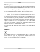
The following diagram shows a typical exhaust system layout. Use this as a guideline to proper exhaust
system installation. Although this diagram just serves as an example, we recommend installation of the
exhaust system by a licensed contractor to meet safety and local code requirements as well as being able
to calculate the correct size blower required for your particular installation. Length of exhaust pipe,
exhaust pipe diameter, number of 90-degree angles, and other restrictions must be calculated when
determining the correct exhaust blower unit. Installing an undersized or oversized blower is not only
unsafe, but it can also lead to
premature and excessive wear
and tear to the laser system.
1
2
3
4
5
6
9
8
3
4
5
6
7
6
8
7
(1) Exhaust blower mounted
outside.
(2) Weatherproof shield
(3) Rigid ducting matching the
diameter of the blower inlet
(4) Reducer to 4 inches
(5) Y-pipe
(6) Shut-off or air-flow gate(s)
(7) Flexible, wire-reinforced,
industrial grade rubber hose
(8) Connection to laser
(9) On/Off switch
Minimum PC Computer Configuration (user supplied)
500 MHz using Windows 95/98 or 2000/XP CD-ROM Drive/Burner
256 MB of RAM Mouse or other pointing device
2 Gigabyte hard drive or bigger 600 DPI Optical Resolution Scanner (optional)
17 inch color VGA monitor Internet connection and email address (optional)
Suggested Software (user supplied)
ULS does not guarantee software compatibility with any off-the-shelf software program that has not been
written by ULS. However, the following suggested programs are widely used by ULS customers and are
considered to be the most functional and compatible programs to use with the laser system.
• Graphics Programs (user supplied)
CorelDRAW, Macromedia Freehand, or Canvas
• Bitmap / Scanning Software (user supplied)
Corel PHOTO-PAINT or Adobe Photoshop