X-660 / X2-660 SuperSpeed-660 Laser Engraving and Cutting Systems Safety, Installation, Operation, and Basic Maintenance Manual Universal Laser Systems, Inc. 16008 North 81st Street Scottsdale, AZ 85260 USA Customer Support Department Phone: 480-609-0297 Fax: 480-609-1203 Web Based Email Support: www.ulsinc.
Notice This publication and its contents are proprietary to Universal Laser Systems, Inc. (ULS), and are intended solely for the contractual use of ULS, Inc. customers. While reasonable efforts have been made to assure the accuracy of this manual, ULS shall not be liable for errors contained herein or for incidental or consequential damage in connection with the furnishing, performance, or use of this material.
Introduction We would like to thank you for your laser system purchase. Universal Laser Systems, Inc. (ULS) is the pioneer, and highest volume manufacturer, of large field, computer controlled laser engraving, marking, and cutting systems. ULS has devoted years of research and development to further the quality of our products that has resulted in a number of remarkable innovations within the laser industry. Since 1988, the staff at ULS has been dedicated to total customer satisfaction.
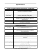
Specifications System Operating Environment Requirements (user provided) Operating Environment Well-ventilated office (recommended) or clean, light-duty manufacturing Operating Temperature 50ºF (10ºC) to 95ºF (35º C) capable 73ºF (22ºC) to 77ºF (25º C) for best performance Storage Temperature 50ºF (10ºC) to 95ºF (35º C) Operating Humidity Non-condensing Electrical Power Single Phase 100/220V AC, 10/5 Amp, 50/60 Hz Grounded (earthed) and stable (surge and spike protected) Particulate/Odor Outside V
Table of Contents Section 1 - Safety Description of Appropriate Use ........................................................................................1-1 General Safety .................................................................................................................1-1 Laser Safety .....................................................................................................................1-2 Safety Labels ........................................................................
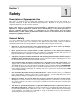
Section 1 Safety Description of Appropriate Use This device is designed for laser cutting and engraving of the materials listed in this manual, in a laboratory, workshop, or light duty manufacturing environment. Materials to be processed must fit completely inside the system for proper operation.
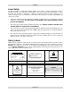
SAFETY Laser Safety The device contains a sealed carbon dioxide (CO2) laser in a Class I enclosure that produces intense invisible and visible laser radiation at a wavelength of 10.6 microns in the infrared spectrum. For your protection, this enclosure is designed to completely contain the CO2 laser beam. Improper use of controls and adjustments, or performance of procedures other than those specified, may invalidate the safety of this system.
SAFETY DANGER WARNING AVOID EXPOSURE INVISIBLE AND VISIBLE LASER RADIATION WHEN OPEN AVOID EYE OR SKIN EXPOSURE TO DIRECT OR SCATTERED RADIATION INVISIBLE LASER RADIATION IS EMITTED FROM THIS APERTURE 221-0017-0 221-0018-0 TURN THE LASER SYSTEM OFF BEFORE CONNECTING OR DISCONNECTING THE ROTARY FIXTURE 221-0019-0 WARNING INPUT POWER: 220 VAC; 50/60 Hz; 15 A TO AVOID RISK OF ELECTRIC SHOCK ALWAYS DISCONNECT POWER CORD BEFORE REMOVING THIS COVER 221-0020-0 221-0021-0 221-0024-0 WARNING THIS SYS
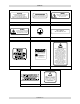
SAFETY 221-0033-0 221-0034-0 221-0016-0 221-0007-0 221-0031-0 221-0044-0 221-0045-0 221-0046-0 221-0047-0 221-0048-0 221-0049-0 221-0050-0 221-0051-0 221-0018-0 221-0012-0 221-0013-0 221-0017-0 221-0018-0 221-0007-0 221-0021-0 221-0016-0 221-0020-0 221-0016-0 221-0037-0 221-0024-0 221-0004-0 221-0015-0 221-0065-0 221-0081-0 Section 1-4
SAFETY EU Compliance (CE) L A S E R S Y S T E M S I N C. Product Identification: X-660, X2-660, and SuperSpeed-660 Laser Engraving and Cutting Systems Manufacturer: Universal Laser Systems, Inc. 16008 N. 81st St. Scottsdale, AZ 85260 Phone: (480) 483-1214 Fax: (480) 483-5620 USA This equipment Is manufactured in conformity with the following directives: 89/336/EEC 73/23/EEC 98/37/EEC (EMC Directive) (Low Voltage Directive) (Machinery Directive) based on the standards listed.
SAFETY FCC Compliance This ULS laser system has been tested and found to comply with Federal Communication Commission (FCC) directives regarding Electromagnetic Compatibility (EMC). In accordance with these directives ULS is required to provide the following information to its customers. FCC Compliance Statement and Warnings This device complied with FCC Rules Part 15. Operation is subject to the following two conditions: 1. This device may not cause harmful interference, and 2.
Section 2 Installation The following operational guidelines are vital to a safe and productive environment. responsibility to provide a proper operating environment. It is your Damage to the laser system due to an inadequate or improper operating environment is considered abuse and WILL NOT be covered under warranty.
INSTALLATION Exhaust System (user supplied) • • • • • • The exhaust system MUST be capable of supplying a minimum of 500 CFM (cubic feet per minute) of airflow while under a load of 6 inches of static pressure (850m3/hr at 1.5kPa). DO NOT install forward incline, backward incline, in-line, or ventilator fans because these types of air handlers are inadequate and inappropriate for this type of installation. A high-pressure blower MUST be used to meet minimum airflow requirements.
INSTALLATION • Raster to Vector Conversion Software (user supplied) Adobe Streamline or CorelTRACE • CAD Software (user supplied) AutoCAD or AutoCAD LT for Windows • FONTS (user supplied) Use True Type fonts ONLY. Do not use PostScript or bitmapped fonts. System Assembly If the doorway is not wide enough to allow to you roll the laser system through it, the system MUST be detached from the cart stand, rotated sideways, passed through the doorway, then re-attached to the cart stand.
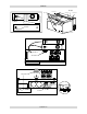
INSTALLATION 6. Locate the cavity where the cables reside. Gently pull the cables upwards and rest them on top of the gray-colored plate as the diagram indicates. 7. Close and re-latch the rear cover. 8. Remove any packing materials or accessories from inside the laser system. 9. Using strong shipping tape or rope, tape the front door closed so that it does not open up when you tilt it. 10.
INSTALLATION Laser Cartridge Installation Before connecting and powering on your system, you must install the laser cartridges. 1) Make sure that your power cord IS NOT plugged in at this time. Press on the backside of the two hinges to release the latch. Gently fold back the rear cover. 2) Locate the laser mounting blocks, the laser latches, and alignment forks. Notice that the alignment forks have two plates, one small and one large. Locate the gap between the two plates.
INSTALLATION Checking Beam Alignment • • • • • Open the top door of the laser system. Locate the power cord and plug it into the system and your grounded electrical outlet. International users may need to connect an adapter to the power cord to be able to plug it into their power source. MAKE SURE THAT YOU ATTACH THE ADAPTER CORRECTLY TO THE POWER CORD AND THAT YOUR POWER SOURCE IS PROPERLY GROUNDED (EARTHED) OTHERWISE SERIOUS DAMAGE CAN OCCUR TO THE LASER SYSTEM.
INSTALLATION USB to Parallel Printer Cable Adapter To use this device, you must have one USB port available in your computer or from a USB hub. The laser system does not have a built-in USB port. However, you can use this adapter to connect the USB part of the adapter to your computer (or hub) and the parallel port end to the laser system. This adapter comes complete with installation software. Please follow the manufacturer’s instructions on how to install and use this device.
INSTALLATION Section 2-8
Section 3 System Operation From the control panel menus and buttons to focusing, loading and unloading materials, this section covers the actual laser engraving and cutting process. If you have done so already, power ON your computer and let it boot up completely BEFORE powering ON the laser system otherwise your laser system can “lock up” when attempting to run the first file and the only way to clear this error is to power the system OFF and then ON again.
SYSTEM OPERATION UP and DOWN: Moves the cursor up or down in the display. Also used to increase or decrease the value of the number that the cursor is positioned on top of. SELECT and ESCAPE: Depending on which menu you are in at the time, SELECT (left) either enters you into that menu item the cursor is currently on, or it toggles that menu item to display different choices.
SYSTEM OPERATION MEMORY CONTROL The laser system is equipped with 16 Megabytes standard and is expandable to 32 Megabytes to store downloaded files while the system is powered ON. Eventually the memory will fill up with files that will need to be deleted to free up space for more files. To delete one file at a time, display the desired file by using PREVIOUS FILE or NEXT FILE buttons. Use the UP or DOWN arrow button to position the cursor on the DELETE THE FILE menu item and then press SELECT.
SYSTEM OPERATION SET FOCUS POSITION Allows you to set the focus position anywhere in the field other than the factory default setting of (1 inch, 1 inch). To change this setting, use the motion control arrow buttons to position the focus carriage in the desired position. Then, bring the cursor down to the YES SAVE POSITION line and press the SELECT. Press the ESCAPE button twice to exit back to the MAIN menu to store this new setting. SET ROTARY AXIS This setting is pre-set at the factory.
SYSTEM OPERATION The following menu is only accessible while the cursor is located in either the READY or the FILE DISPLAY menus. It is not accessible if the cursor is in the DOS POWER SETTINGS or the PREFERENCES menus. ORIGIN POSITION Menu (X-Y button) The default origin position is the (0,0) position of the rulers. To position the origin to any other point in the engraving area, press the X-Y button and the red laser diode will appear on the engraving table.
SYSTEM OPERATION Focus Tool Method 3 Place your material into the upper left corner of the engraving field against the rulers. Visually make sure that the height of the material will not interfere with the focus carriage when it moves over the material. While either the READY or FILE DISPLAY menu is displayed, press the Z button. The focus carriage will move to the upper left corner of the engraving area.
SYSTEM OPERATION Material Thickness (Z POSITION) Method Press the Z button. Verify that the CURRENT LENS displayed is the same as the one being used. If not, position the cursor on the second line in the display and press the SELECT button to toggle through the choices. When the correct lens is displayed, re-position the cursor to the top line and then over to the first or second digit. Raise or lower the table until the display shows the material thickness either in inch or metric units.
SYSTEM OPERATION Making a Sample, Step-by-Step We will now illustrate how to use the laser system to create a product from start to finish. As an example, we will raster engrave and vector cut a key chain from a 2 by 4 inch, 1/8 inch thick piece of hardwood. It is preferable to use a hardwood such as Cherry or Walnut as opposed to grainy wood such as Oak or a manufactured product such as plywood or melamine.
SYSTEM OPERATION Step 4 - Starting the Engraving Process • • • • • Turn ON the exhaust system. Make sure the material is positioned correctly within the engraving area. Make sure the system is properly focused. Make sure the top door is closed. Press the START button to begin laser processing. WARNING: Observe that the laser system is functioning as desired.
SYSTEM OPERATION How it All Works There are five (5) basic components that make up a laser system, the control panel, the CPU, the DC power supply, the laser cartridge, and the motion system. DC Power Supply LASER CARTRIDGE The DC power supply converts the incoming AC electricity to 48 volts DC. This is used to power both the laser cartridge and the CPU. CPU The CPU is the “brains” of the system and controls everything. Located on the CPU are standard computer memory SIMMS.
SYSTEM OPERATION The focal range of the lens, where the beam is considered to be “in focus”, is equivalent to +/- 5% above and below the focus point. Shorter lenses produce a smaller spot size but also have a very narrow focal range. This means that it would only be useful for engraving very flat objects. The longer lenses have a much wider range of focus but also produce a larger spot size that would prohibit the engraving of fine detail.
SYSTEM OPERATION Single/Dual Laser Single Beam Mode In the X-600 model, there is only one laser present so the system will always operate in Single Laser Single Beam mode. If you have an X2-600 and only purchased one laser, your system also operates the same as the X-600, but gives you the opportunity to add a laser in the future.
SYSTEM OPERATION When vectoring, Dual Beam mode automatically turns off, even if you have the checkbox selected. This is because you would never want to vector engrave or cut with two separate beams. In the diagram, the engraving density is the separation distance between each laser beam relative to the top and bottom of the engraving field. The illustration of the focus carriage has been rotated 90 degrees for clarity.
SYSTEM OPERATION Section 3-14
Section 4 Basic Maintenance Keeping the laser system clean will ensure the highest quality engraving. The frequency of cleaning will depend entirely on the type of material being engraved, the performance of your exhaust system, the operating environment, and the amount of laser system usage over a given period of time. Dirt or debris that is allowed to build up on the motion system components will cause uneven or rough engraving, or loss of engraving position as well as premature component failure.
BASIC MAINTENANCE Cleaning and Maintenance Supplies • • • • • Soap solution mixture of 1 tablespoon (2 cl) liquid soap and 1 quart (liter) of water in a spray bottle Paper towels Cotton cloth Denatured alcohol (NOT to be used on any painted surface, plastic, or the Top Window) Acetone (can be used on the engraving table but nowhere else) CAUTION When using acetone or denatured alcohol, please follow the instructions on the printed label of these materials for safe handling procedures.
BASIC MAINTENANCE #2 Mirror To gain access to the #2 mirror, the mirror cover must be removed. Remove the thumbscrew and slide the cover to the right and then lift the cover straight up. Inspect the #2 mirror and clean it only if there is debris present. To clean the #2 mirror with a cotton swab, moisten the cotton swab with the lens cleaning solution supplied with the laser system. DO NOT use other types of cleaners or solutions. Gently roll the cotton swab across the mirror once.
BASIC MAINTENANCE If your system is equipped with Air Assist, using your fingers, rotate the beam window cover counter-clockwise (B) and then off at a 45-degree angle. If the beam window cover is stuck use a 1/16 Allen wrench to loosen or remove the screw (A) and try again. Set the cover off to the side and clean the optic, if necessary. Reinstall the beam window cover opposite of removal being careful not to scratch the optic. Exhaust Plenum Cleaning • • • • • Power system ON.
BASIC MAINTENANCE Adjustments and Lubrication There are no periodic adjustments normally required. The bearings in the motion system will self adjust to take up any clearances as they begin to wear. The belts are fiber reinforced and will not stretch under normal use so that periodic tension adjustment is not necessary. Optical alignment is not necessary because the laser and the #2 mirror are fixed. All bearings in the system are sealed and do not require lubrication.
BASIC MAINTENANCE Troubleshooting Guide Engraving Quality Problem “Fuzzy” looking raster engraving or small text appears like a “double image” Fine detail is missing such as the serif’s of characters or thin lines of script fonts when raster engraving Vertical or diagonal background pattern present when raster engraving large areas and/or large amounts of material Horizontal background pattern present when raster engraving large areas and/or large amounts of material • Possible Cause Dirty laser syste
BASIC MAINTENANCE Raster engraving appears sharp on both ends of the engraving but fuzzy in the middle Engraving does not appear as deep as it normally does • Dirty laser system • • Something is loose System needs tuning • • • Worn X-axis belt and/or drive gear Faulty laser tube Graphic, graphic software, graphic software setup, color palette, monitor display colors, or driver settings have changed • • Out of focus Material or material density has changed Settings have changed • • • • • • Engravi
BASIC MAINTENANCE Wavy lines when vector engraving or cutting Angled cuts when cutting through thick materials such as ¼” acrylic • Running too fast • • Dirty laser system • • Worn or faulty bearings • • Arm is out of square • • Firmware needs to be updated • • Angled cuts are a normal condition if they are equal on all sides of the object. The topside of the object will always be slightly smaller than the backside of the object due to the material “spreading more” at the focal point.
BASIC MAINTENANCE Operational • Mechanical interference • • Dirty laser system • • CPU overheating • • • • • • • • • X-belt too tight Worn or binding X-axis bearings Worn or binding X-axis idler pulley Worn or binding X-axis motor Firmware needs updating Bent Y-flag Dirty or faulty home sensor(s) Dirty or faulty Z-axis sensor • • • • • • • • When using Autofocus, the table moves all the way down to the bottom and gets stuck • • Autofocus sensor or reflector is dirty Autofocus sensor is misali
BASIC MAINTENANCE Section 4-10
Section 5 Material Settings Guide This section provides sample driver settings and helpful hints to get started engraving and/or cutting the materials listed. Safety NEVER LEAVE THE LASER SYSTEM RUNNING UNATTENDED FOR ANY REASON. Exposure to the laser beam can cause ignition of combustible materials. All laser cutting and engraving should be constantly supervised. NEVER OPERATE THE LASER SYSTEM WITHOUT A PROPERLY INSTALLED AND OPERATING EXHAUST SYSTEM.
MATERIAL SETTINGS GUIDE • Laser engraving or cutting materials other than those described in this manual can be a safety hazard and can damage the laser system. • Damages to the laser system due to neglect, misuse, or operator error ARE NOT covered under warranty. • Damage to the laser system due to an inadequate or improper operating environment is considered abuse and ARE NOT covered under warranty.
MATERIAL SETTINGS GUIDE NOTE When engraving very small objects, top speed cannot be achieved because acceleration and deceleration of the motion system requires time and distance. The laser system will automatically adjust itself to a maximum engraving speed that it can achieve due to the size and position of the graphic. This is why you might notice that there might be no difference in engraving time on certain graphics whether you choose 100% speed or less.
MATERIAL SETTINGS GUIDE ACRYLIC - CAST AND EXTRUDED LIGHT RASTER ENGRAVING LASER WATTAGE 25 30 35 40 45 50 55 60 POWER 53 44 38 34 30 27 24 22 SPEED 100 100 100 100 100 100 100 100 PPI 500 500 500 500 500 500 500 500 PASS 1 1 1 1 1 1 1 1 DEPTH .002” .002” .002” .002” .002” .002” .002” .002” DEEP RASTER ENGRAVING LASER WATTAGE 25 30 35 40 45 50 55 60 POWER 100 100 100 100 100 100 100 100 SPEED 60 64 68 73 77 81 86 90 PPI 500 500 500 500 500 500 500 500 PASS 1 1 1 1 1 1 1 1 DEPTH .010” .010” .
MATERIAL SETTINGS GUIDE COMMENTS There are two types of acrylic available, cast and extruded. Cast turns white or frosted and extruded remains clear when engraved. Use extruded acrylic for paint filled engraving and cast for regular engraving. Cast engraves better without masking. Lightly engrave the surface to frost it with a low power setting such as the first setting listed above.
MATERIAL SETTINGS GUIDE ACRYLIC - MIRRORED LIGHT RASTER ENGRAVING LASER WATTAGE 25 30 35 40 45 50 55 60 POWER 58 49 43 40 35 32 29 27 SPEED 100 100 100 100 100 100 100 100 PPI 500 500 500 500 500 500 500 500 PASS 1 1 1 1 1 1 1 1 DEPTH .003” .003” .003” .003” .003” .003” .003” .003” DEEP RASTER ENGRAVING LASER WATTAGE 25 30 35 40 45 50 55 60 POWER 100 100 100 100 100 100 100 100 SPEED 60 64 68 73 77 81 86 90 PPI 500 500 500 500 500 500 500 500 PASS 1 1 1 1 1 1 1 1 DEPTH .010” .010” .010” .010” .
MATERIAL SETTINGS GUIDE COMMENTS Engraving mirrored acrylic is similar to engraving regular acrylic. The idea is to engrave through the mirrored backing enough to begin to penetrate into the acrylic. Engraving deeply will cause a crusty residue to form just like with non-mirrored acrylic. A double image will appear if engraving on the front side of the mirror. It is not necessary to mask the backside when engraving because the mirrored backing shields the acrylic from smoke damage.
MATERIAL SETTINGS GUIDE ANODIZED ALUMINUM RASTER ENGRAVING LASER WATTAGE 25 30 35 40 45 50 55 60 POWER 72 60 52 45 40 36 32 30 SPEED 100 100 100 100 100 100 100 100 PPI 500 500 500 500 500 500 500 500 PASS 1 1 1 1 1 1 1 1 DEPTH .001” .001” .001” .001” .001” .001” .001” .001” VECTOR ENGRAVING LASER WATTAGE 25 30 35 40 45 50 55 60 POWER 12 10 9 8 7 6 5 4 SPEED 4.0 4.0 4.0 4.0 4.0 4.0 4.0 4.0 PPI 1000 1000 1000 1000 1000 1000 1000 1000 PASS 1 1 1 1 1 1 1 1 DEPTH .001” .001” .001” .001” .001” .
MATERIAL SETTINGS GUIDE BRASS - PAINTED RASTER ENGRAVING LASER WATTAGE 25 30 35 40 45 50 55 60 POWER 29 27 25 23 21 19 17 15 SPEED 100 100 100 100 100 100 100 100 PPI 500 500 500 500 500 500 500 500 PASS 1 1 1 1 1 1 1 1 DEPTH .001” .001” .001” .001” .001” .001” .001” .001” VECTOR ENGRAVING LASER WATTAGE 25 30 35 40 45 50 55 60 POWER 6 5 4 3 3 3 2 2 SPEED 4.0 4.0 4.0 4.0 4.0 4.0 4.0 4.0 PPI 1000 1000 1000 1000 1000 1000 1000 1000 PASS 1 1 1 1 1 1 1 1 DEPTH .001” .001” .001” .001” .001” .001” .
MATERIAL SETTINGS GUIDE CORIAN / AVONITE / FOUNTAINHEAD RASTER ENGRAVING LASER WATTAGE 25 30 35 40 45 50 55 60 POWER 100 100 100 100 100 100 100 100 SPEED 44 53 61 70 79 88 95 100 PPI 500 500 500 500 500 500 500 500 PASS 1 1 1 1 1 1 1 1 DEPTH .005” .005” .005” .005” .005” .005” .005” .005” DEEP RASTER ENGRAVING LASER WATTAGE 25 30 35 40 45 50 55 60 POWER 100 100 100 100 100 100 100 100 SPEED 13 15 18 20 23 26 28 30 PPI 1000 1000 1000 1000 1000 1000 1000 1000 PASS 1 1 1 1 1 1 1 1 DEPTH .015” .
MATERIAL SETTINGS GUIDE CORK RASTER ENGRAVING LASER WATTAGE 25 30 35 40 45 50 55 60 POWER 80 80 80 80 80 80 80 80 SPEED 38 45 52 60 67 75 84 90 PPI 500 500 500 500 500 500 500 500 PASS 1 1 1 1 1 1 1 1 DEPTH .010” .010” .010” .010” .010” .010” .010” .010” VECTOR ENGRAVING LASER WATTAGE 25 30 35 40 45 50 55 60 POWER 12 10 9 8 7 6 5 4 SPEED 4.0 4.0 4.0 4.0 4.0 4.0 4.0 4.0 PPI 500 500 500 500 500 500 500 500 PASS 1 1 1 1 1 1 1 1 DEPTH .010” .010” .010” .010” .010” .010” .010” .
MATERIAL SETTINGS GUIDE DELRIN RASTER ENGRAVING LASER WATTAGE 25 30 35 40 45 50 55 60 POWER 100 100 100 100 100 100 100 100 SPEED 22 26 30 35 39 44 48 52 PPI 500 500 500 500 500 500 500 500 PASS 1 1 1 1 1 1 1 1 DEPTH .015” .015” .015” .015” .015” .015” .015” .015” VECTOR CUTTING LASER WATTAGE 25 30 35 40 45 50 55 60 POWER 75 75 75 75 75 75 75 75 SPEED 2.0 2.4 2.8 3.2 3.6 4.0 4.4 4.8 PPI 200 200 200 200 200 200 200 200 PASS 1 1 1 1 1 1 1 1 DEPTH .060” .060” .060” .060” .060” .060” .060” .
MATERIAL SETTINGS GUIDE GLASS / CRYSTAL RASTER ENGRAVING LASER WATTAGE POWER 25 100 30 100 35 100 40 100 45 100 50 100 55 100 60 100 COMMENTS: Engrave at Image Density 4. VECTOR ENGRAVING LASER WATTAGE 25 30 35 40 45 50 55 60 POWER 10 10 10 10 10 10 10 10 SPEED 13 15 18 20 23 26 28 30 PPI 300 300 300 300 300 300 300 300 PASS 1 1 1 1 1 1 1 1 DEPTH .001 .001 .001 .001 .001 .001 .001 .001 SPEED 3.3 4.0 4.6 5.3 5.9 6.6 7.3 7.9 PPI 300 300 300 300 300 300 300 300 PASS 1 1 1 1 1 1 1 1 DEPTH .001 .001 .
MATERIAL SETTINGS GUIDE LEATHER RASTER ENGRAVING LASER WATTAGE 25 30 35 40 45 50 55 60 POWER 45 38 33 28 25 23 20 19 SPEED 100 100 100 100 100 100 100 100 PPI 500 500 500 500 500 500 500 500 PASS 1 1 1 1 1 1 1 1 DEPTH .001” .001” .001” .001” .001” .001” .001” .001” VECTOR ENGRAVING LASER WATTAGE 25 30 35 40 45 50 55 60 POWER 6 5 4 4 3 3 3 3 SPEED 4.0 4.0 4.0 4.0 4.0 4.0 4.0 4.0 PPI 500 500 500 500 500 500 500 500 PASS 1 1 1 1 1 1 1 1 DEPTH .001” .001” .001” .001” .001” .001” .001” .
MATERIAL SETTINGS GUIDE MARBLE RASTER ENGRAVING LASER WATTAGE 25 30 35 40 45 50 55 60 VECTOR ENGRAVING LASER WATTAGE 25 30 35 40 45 50 55 60 POWER 100 100 100 100 100 100 100 100 SPEED 35 42 48 55 62 69 77 82 PPI 500 500 500 500 500 500 500 500 PASS 1 1 1 1 1 1 1 1 DEPTH .003” .003” .003” .003” .003” .003” .003” .003” POWER 24 20 17 15 13 12 SPEED 4.0 4.0 4.0 4.0 4.0 4.0 4.0 4.0 PPI 500 500 500 500 500 500 500 500 PASS 1 1 1 1 1 1 1 1 DEPTH .003” .003” .003” .003” .003” .003” .003” .
MATERIAL SETTINGS GUIDE MAT BOARD RASTER ENGRAVING LASER WATTAGE 25 30 35 40 45 50 55 60 POWER 72 60 52 45 40 36 32 30 SPEED 80 80 80 80 80 80 80 80 PPI 250 250 250 250 250 250 250 250 PASS 1 1 1 1 1 1 1 1 DEPTH .005” .005” .005” .005” .005” .005” .005” .005” VECTOR ENGRAVING LASER WATTAGE 25 30 35 40 45 50 55 60 POWER 24 20 17 15 13 12 11 10 SPEED 4.0 4.0 4.0 4.0 4.0 4.0 4.0 4.0 PPI 250 250 250 250 250 250 250 250 PASS 1 1 1 1 1 1 1 1 DEPTH .005” .005” .005” .005” .005” .005” .005” .
MATERIAL SETTINGS GUIDE MELAMINE - STANDARD ENGRAVING LIGHT RASTER ENGRAVING LASER WATTAGE 25 30 35 40 45 50 55 60 POWER 100 100 100 100 100 100 100 100 SPEED 25 30 34 39 44 50 55 59 PPI 500 500 500 500 500 500 500 500 PASS 1 1 1 1 1 1 1 1 DEPTH .015” .015” .015” .015” .015” .015” .015” .015” DEEP RASTER ENGRAVING LASER WATTAGE 25 30 35 40 45 50 55 60 POWER 100 100 100 100 100 100 100 100 SPEED 17 21 24 27 31 35 38 41 PPI 500 500 500 500 500 500 500 500 PASS 1 1 1 1 1 1 1 1 DEPTH .020” .020” .
MATERIAL SETTINGS GUIDE MELAMINE - PHOTO/CLIPART ENGRAVING RASTER ENGRAVING LASER WATTAGE POWER SPEED 25 80 38 30 80 45 35 80 52 40 80 60 45 80 67 50 80 75 55 80 84 60 80 90 COMMENTS: Engrave unmasked. Use an Image Density of 5. PPI 500 500 500 500 500 500 500 500 PASS 1 1 1 1 1 1 1 1 DEPTH .008” .008” .008” .008” .008” .008” .008” .008” RASTER ENGRAVING LASER WATTAGE POWER SPEED 25 80 25 30 80 30 35 80 35 40 80 40 45 80 45 50 80 50 55 80 56 60 80 60 COMMENTS: Engrave unmasked.
MATERIAL SETTINGS GUIDE PLASTIC - ENGRAVERS MICROSURFACED RASTER ENGRAVING LASER WATTAGE 25 30 35 40 45 50 55 60 POWER 29 27 25 23 21 19 17 15 SPEED 100 100 100 100 100 100 100 100 PPI 500 500 500 500 500 500 500 500 PASS 1 1 1 1 1 1 1 1 DEPTH .001” .001” .001” .001” .001” .001” .001” .001” VECTOR CUTTING LASER WATTAGE 25 30 35 40 45 50 55 60 POWER 60 50 43 38 34 30 27 25 SPEED 1.2 1.2 1.2 1.2 1.2 1.2 1.2 1.2 PPI 150 150 150 150 150 150 150 150 PASS 1 1 1 1 1 1 1 1 DEPTH .060” .060” .060” .
MATERIAL SETTINGS GUIDE RUBBER STAMPS RASTER ENGRAVING LASER WATTAGE 25 30 35 40 45 50 55 60 POWER 100 100 100 100 100 100 100 100 SPEED 10 12 14 16 17 20 22 23 PPI 500 500 500 500 500 500 500 500 PASS 1 1 1 1 1 1 1 1 DEPTH .030” .030” .030” .030” .030” .030” .030” .030” PERFORATED VECTOR CUTTING LASER WATTAGE 25 30 35 40 45 50 55 60 POWER 60 60 60 60 60 60 60 60 SPEED 1.3 1.6 1.8 2.1 2.3 2.6 2.9 3.1 PPI 90 90 90 90 90 90 90 90 PASS 1 1 1 1 1 1 1 1 DEPTH .040” .040” .040” .040” .040” .040” .
MATERIAL SETTINGS GUIDE SIGN VINYL RASTER ENGRAVING LASER WATTAGE 25 30 35 40 45 50 55 60 POWER 100 100 100 100 100 100 100 100 SPEED 19 23 26 30 34 38 42 45 PPI 500 500 500 500 500 500 500 500 PASS 1 1 1 1 1 1 1 1 DEPTH .015” .015” .015” .015” .015” .015” .015” .015” VECTOR CUTTING (KISS CUT) LASER WATTAGE 25 30 35 40 45 50 55 60 POWER 5 5 5 5 5 5 5 5 SPEED 3.3 4.0 4.7 5.3 6.0 6.7 7.4 8.1 PPI 500 500 500 500 500 500 500 500 PASS 1 1 1 1 1 1 1 1 DEPTH .003” .003” .003” .003” .003” .003” .003” .
MATERIAL SETTINGS GUIDE WOOD RASTER ENGRAVING LASER WATTAGE 25 30 35 40 45 50 55 60 POWER 100 100 100 100 100 100 100 100 SPEED 25 30 34 39 44 50 55 59 PPI 500 500 500 500 500 500 500 500 PASS 1 1 1 1 1 1 1 1 DEPTH .020” .020” .020” .020” .020” .020” .020” .020” VECTOR ENGRAVING LASER WATTAGE 25 30 35 40 45 50 55 60 POWER 80 80 80 80 80 80 80 80 SPEED 4.2 5.0 5.9 6.7 7.6 8.4 9.2 10.1 PPI 500 500 500 500 500 500 500 500 PASS 1 1 1 1 1 1 1 1 DEPTH .030” .030” .030” .030” .030” .030” .030” .
MATERIAL SETTINGS GUIDE Elevating the wood also helps to determine whether the laser has passed completely through since the cut pieces will fall through to the table when cutting is finished. Also, set up the drawing so that the inner pieces of the drawing are cut first, otherwise pieces may fall through at the wrong time. Not all wood finishes are created equal. When ordering wood from a supplier, be sure to specify that it is being used for laser engraving.
MATERIAL SETTINGS GUIDE Section 5-24
Section 6 Accessories There are optional accessories, not included with the basic laser system, that are available at additional cost. Instructions on how to use these accessories are included in this section. The user can purchase and install all accessories, except Air Assist, which is a factory installed option ONLY. CAUTION: Before attempting to use any accessory, make sure that you have read the entire manual up to this point.
ACCESSORIES Making the Connections Standard Air Assist style In the left rear part of the system you will find the pressure gauge (1), flow adjustment valve (2), quick release coupling (3), and release lever (4). Push in the release lever and pull down on the quick release coupling to remove it from the machine. Attach your compressed air supply hose to this fitting (1/4 NPT threads) and use Teflon tape on the threads to prevent leaks. Re-insert the fitting until it “clicks” into place.
ACCESSORIES Locate the locking ever (1) attached to both fittings. Push in the lever until it clicks. Attach the larger quick release coupling (3) (1/4 NPT threads) to your compressed air supply line (4). Use Teflon tape on the threads to prevent leaks. Push the quick release coupling (3) into the fitting (2) until it clicks into place. Attach the other end of the supply line (4) to a particulate filter (5), desiccant/dryer (6), and then to an oil-free compressed air source (7).
ACCESSORIES NOTE: Air will always be flowing through the system as long as the compressed air source is turned ON. We recommend installing a shut off valve in between your compressed air supply and the laser system. Before you run your material, we suggest that you adjust your air and/or gas flow. To do this, you must first turn on your compressed air source so that there is flow through the system. Now, either turn the laser system ON or leave it OFF.
ACCESSORIES When you press the “Start” button on the laser system, the Air Assist control box will send out a +5 VDC signal through the AUX OUT control wire, which can be used to turn ON the Air Compressor (optional) and will keep the Air Compressor ON until the file completes. This type of control saves electricity, reduces the running time of the compressor, and reduces ambient noise when the laser system is not running.
ACCESSORIES Once you have set your flow rates for each pathway that you will be using, reset the laser systems control panel so that the “AIR ASSIST” option displays “AUTO”. This will allow your selections in the printer driver to activate the correct solenoid valve choices. Programming the PC Printer Driver The Air Assist option provides printer driver controlled activation and deactivation of solenoid valves that direct the flow through one of three paths with its final destination being the cone.
ACCESSORIES Cone Alignment Check and Adjust (both styles) • • • • • • • • • Power the laser system ON. Open the top door. 2.0 Position the focus carriage in the middle of the field. Turn ON the red diode laser pointer. Place a piece of paper (1) underneath the cone and observe the position of the red beam (2) in relation to the center of the bottom of the Cone (3) and be sure to check it from the front and side.
ACCESSORIES Removal, Cleaning, and Replacement of the Filter • Turn the Air Compressor OFF and unplug it. • Unscrew the cover by turning it 1/8 turn counterclockwise like you were unscrewing a jar, and pull down. The clear plastic container might still remain attached to the top. Gently pull this part straight down. • You will see a red colored foam filter. Unscrew the filter, and wash it out with water. Make sure that it is completely dry, then reinstall.
ACCESSORIES How it Works With the Dual Head installed, the special “Beam Splitter” optic inside of the Dual Head splits the laser beam in half. It reflects one half of the laser beam’s energy down through the focus lens inside the Dual Head and passes the other half of the laser beams power through the beam splitter. The laser beam goes through the beam tube and then onward through to the single heads #3 mirror where the laser beam is reflected downward through the single head’s focus lens.
ACCESSORIES • If there is a button head screw located on the top of the Dual Head and or the single head, remove it. L R Beam Tube 2.0 DUAL HEAD • • 2.0 Pick up the Dual Head tube and note the “L” (Left) and “R” (Right) markings. Install the tube using the supplied thumbscrews and tighten securely. If you have the Air Assist option, locate the 1 (one) black thumbscrew on the side of the Single Head.
ACCESSORIES Operation NOTE: In the following example, we will assume that your laser engraving system is a “V Platform” that has a maximum engraving area of 24” x 18” Landscape mode. • • • • • • Turn ON your computer (if it is not ON already). Start your graphics program, create a new graphic or open an existing graphic. Select “Print”, choose your printer (if the laser system is not set as your default), and select “Properties” to bring up the Printer Driver settings.
ACCESSORIES • • • • Open the front door of the laser system and carefully slide the cutting table into the laser system so that its body is squarely pushed up against the engraving table rulers on the top and the side of the table. The rulers of the cutting table should now overlap the rulers on the engraving table. Slide the adjustable manifold squarely up against the exhaust plenum and tighten the four (4) screws on the side of the cutting table.
ACCESSORIES Focus Lens Kits There are three optional Focus Lens Kits available other than the standard 2.0”, they are the 1.5”, 2.5”, and the 4.0” kits. Included in these kits are the focus lens, #3 mirror, front plate, thumbscrews, and a focus tool. Different lenses produce different spot sizes and have different focal ranges. For example, the 1.5” lens produces a spot size of .003” and has an effective focal range of +/- .075”.
ACCESSORIES • Place the bracket on the table (1). Insert the thumbscrews and washers (2) into the screw holes but do not tighten down completely. Leave the thumbscrews loose enough so that the bracket can slide. 1 2 3 4 5 6 7 8 9 10 11 12 13 14 15 16 17 18 19 20 21 22 23 24 1 1 2 2 3 4 1 5 6 7 8 9 10 11 12 • • Place the Rotary Fixture on a flat surface. Using an Allen wrench, attach the two socket head shoulder screws (1) to the side of the base plate.
ACCESSORIES 3 1 2 • • You must now focus on the glass. Power ON the laser system and wait for the display to show “READY”. Press the “Z” button on the control panel and notice that the motion system will align to the centerline of the Rotary Fixture automatically. You will also notice that the left and right arrow buttons will cause the focus carriage to move left and right respectively. This control is the same as when engraving a flat object on the table.
ACCESSORIES In this example our upper limit is about 20500X and the lower limit is 19000X. This translates to 20.5 inches and 19.0 inches respectively because the coordinates are in 1/1000 inch units. We have now set up the glass to be engraved. Close all doors of the laser system, go to your computer, and open your graphics software. Printer Driver Settings With your graphics software open, proceed immediately to “Printer Setup” and open the printer driver.