VersaLASER® (VLS) User Guide VLS2.30, VLS3.50 www.ulsinc.
©2010 Universal Systems, Inc. All Rights Reserved. Universal Laser Systems logo and name are registered trademarks, and VersaLASER, High Power Density Focusing Optics, Rapid Reconfiguration, 1-Touch Laser Photo and Laser Interface + trademarks of Universal Laser Systems, Inc. All other company and product names are trademarks or registered trademarks of their respective companies. Universal’s laser systems are protected under one or more of U.S.
Thank you for choosing Universal Laser Systems®. We appreciate innovative customers like you who have made Universal Laser Systems an integral part of their business. Universal Laser Systems is committed to providing the highest level of customer satisfaction and support. To ensure your satisfaction, we urge you to read the documentation provided with your equipment. Since 1988, Universal Laser Systems has been committed to continually improving our technology and customerdriven laser solutions.
Table of Contents USER GUIDE CD Chapter 1 – Specifications 5 Chapter 2 – Safety 8 Chapter 3 – Installation 16 Chapter 4 – Operation 28 Chapter 5 – Accessories 44 Chapter 6 – Maintenance 62 Software Your Reference Guide contains the Software Installation CD. Please follow the instructions for proper installation. Warranty Your Reference Guide contains Warranty documents pertaining to your purchase.
Chapter 1 - Specifications 5
VLS2.30 VLS3.
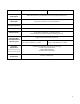
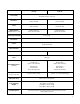
VLS2.30 Laser Safety VLS3.50 CO2 Laser, Interlocked Safety Enclosure = Class 1 Red Diode Pointer = Class 3R Work Area* 16 x 12 in (406 x 305 mm) 24 x 12 in (610 x 305 mm) Table 18.75 x 14.5 in (476 x 368 mm) 26.75 x 14.60 in (679 x 368 mm) Maximum Part (WxHxD) with 1.5” lens 18.75 x 14.5 x 4 in (476 x 368 x 102 mm) 26.75 x 14.
Chapter 2 - Safety 8
Description of Appropriate Use This device is designed for laser cutting and engraving in an office, laboratory, workshop or light duty manufacturing environment. Materials to be processed must fit completely inside the system for proper operation.
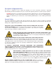
DANGEROUS VOLTAGES ARE PRESENT WITHIN THE ELECTRONICSENCLOSURES OF THIS SYSTEM. Access to these areas is not necessary during normal operation. If it becomes necessary to open one of these enclosures for service reasons, please remember to disconnect the power cord from your electrical supply. NEVER REMOVE THE GROUND LEAD TO THE ELECTRICAL CORD AND PLUG THE SYSTEM INTO A NON-GROUNDED OUTLET.
Tamper Proof Labels All laser cartridges are equipped with tamper proof labels. There are NO field serviceable parts inside a Universal Laser System, Inc. (ULS) laser cartridge. If your laser cartridge needs service, please contact the ULS Customer Service Team at 480-609-0297 (USA), +43 1 402 22 50 (Austria), +81 (45) 224-2270 (Japan) or e-mail us at support@ulsinc.com.
z Front View 12
Back View Back view with laser cover removed 13
EU Declaration of Conformity Product Identification: VersaLASER System Manufacturer: Universal Laser Systems, Inc. 16008 N. 81st St.
FCC Compliance This ULS laser system has been tested and found to comply with Federal Communication Commission (FCC) directives regarding Electromagnetic Compatibility (EMC). In accordance with these directives, ULS is required to provide the following information to its customers. FCC Compliance Statement and Warnings This device complied with FCC Rules Part 15. Operation is subject to the following two conditions: 1. This device may not cause harmful interference, and 2.
Chapter 3 - Installation 16
This section provides step-by-step instructions for site preparation, computer/software setup and laser system assembly and connection. Follow the instructions in the order shown. 1. Site Preparation 2. Operating System Requirements and Software Installation 3. Assembling and Connecting Your Laser System Note: Make sure to complete step 2 (software installation) prior to plugging the laser system into a USB port on your PC.
4. The laser system is designed as a Class I, Group A, pluggable device. It is also designed for connection to IT Power systems which provide the most flexibility to the user. Step 2: Computer Requirements and Software Installation Your computer is a critical component in the operation of your laser system. In fact, you cannot operate the laser system if your computer is not connected, powered on, running Windows and running the Universal Control Panel (UCP) software.
Computer Power Management Power management settings on your computer can interfere with proper operation of the laser system by putting the PC in standby or sleep mode while the laser system is processing material. The settings can be controlled through the power options in the Windows control panel on your PC. The illustrations below show you how to disable power management. XP Vista and 7 For the Power Scheme in use, select “Never” for all the options: Turn off display and Put the computer to sleep.
Software Installation At this point you need to install the Universal Control Panel (UCP) and printer driver. In order to install the software, you need to have administrative privileges on the computer before starting installation. Use the Software Installation CD-ROM included with your laser system. 1. Insert the Software Installation CD-ROM into your PC’s CD/DVD drive. It should automatically launch the “Universal Control Panel Installation” window.
Step 3: Assembling and Connecting Your Laser System Familiarize yourself with the instructions before getting started. The final step in installation is to assemble your laser system, install the laser cartridge(s), make final connections and perform a beam alignment check. Do not power up your laser system until the final step, “Checking Beam Alignment.” Laser System Assembly 1. Unpack the air filtration unit and place it on a level surface. 2.
5. Open the top door and remove any packaging from inside the machine. 6. Gently move the X-Axis arm (1) back and forth. It should slide freely. 1 7. Bend and connect the short exhaust hose provided with the air filtration unit to the exhaust port on the back of the laser system and secure it with the provided hose clamps. Once the hose is attached, install the provided sheet metal cover over the exhaust hose. 8.
9. In some instances the laser must be installed in the laser system. If the laser is not already installed in the laser system, locate the laser and follow these instructions to install it, otherwise skip to step 10. a. Remove the back cover from the laser system by removing the two screws on the left and right side of the cover. b. Locate the two mounting blocks shown with arrows below and the laser connector on the left side of the laser compartment. c.
d. Pick up the laser cartridge by the ends and mount the cartridge onto the mounting blocks shown in step b by placing the upper “V” groove on top of the mounting blocks. Slide the cartridge to the right or left as necessary until the mounting holes in the top of the laser line up with the mounting holes in the top of the laser mounting block. e. Attach the two supplied mounting screws marked 1 above, the supplied securing bracket marked 2 and the laser connector marked 3. f. Replace the back cover.
10. Attach a power cord to the air filtration unit’s power inlet (5). 11. Connect the provided 3 ft. communications cable between one of the two Serial ports (2) of the laser system and the Serial port connector on the air filtration unit (3). Secure the Serial cable using the retainer clips (4). 12. Attach a power cord to the laser system’s power inlet (6). 13. Connect both air filtration and laser system power cords into a grounded outlet. 14.
15. After connecting the USB cord, the “Found New Hardware Wizard” will open to install the drivers for the USB connection. If the wizard offers to connect to “Windows Update” to search for software, select “No, not at this time.” Then select “Next” to continue. a. Select “Install the software automatically.” Then Select “Next” to continue. You do not need to insert the Software Installation CD-ROM. b. Select “Finish” to close the Wizard.
Checking Beam Alignment As a final step in the installation process you need to check your beam alignment. You do this using the red pointer beam. 1. Open the top door and rotate the x axis arm cover up and out of the way. 2. Place a small piece of masking tape across the 3/4” (19 mm) hole in the focus carriage (1). Gently rub the tape around the edge of the hole so that you can see the outline of the hole through the tape (2). 3.
Chapter 4 – Operation 28
Important Overview CAUTION: Please refer to the Safety section before operating the laser system. All ULS laser systems are designed to operate like a computer printer. The laser systems are provided with two software components designed for Microsoft Windows based operating systems. The first component is a printer driver that allows you to print from any Windows based graphic software capable of printing through the Windows print system.
The Printer Driver Interface The printer driver is a piece of software that allows you to create jobs for the laser system using the Windows print system. The printer driver has a preferences dialog with two tabs which allow you to set various parameters for a print job. Materials Database Printer Driver Tab This tab of the printer driver automatically calculates the appropriate laser job settings for a nominal effect based on the material selected and the maximum output power of the laser installed.
Units This section allows you to switch between Metric and English units. Fixture Type None If you are not using any type of fixture, set the drop down menu to NONE. Rotary If you have purchased this accessory, read how to install and operate this fixture in the Accessories section of the User Guide.
Default Button The Default button will reset the driver settings to factory default values. You may abort these changes by selecting Cancel; selecting OK or APPLY will approve the changes. Cancel Button The Cancel button closes the printer driver settings interface window and takes you back to the previous window without saving changes made to the settings. Apply Button The APPLY button saves all changes made to the printer driver settings.
The Universal Control Panel (UCP) When a graphic has been printed through the printer driver a laser job is created and passed to the queue in a piece of software called the Universal Control Panel (UCP). The UCP software provides a convenient interface for interacting with and controlling your laser system. Once you have installed the UCP, a red diamond-shaped icon will appear in the lower right corner of your Windows taskbar.
Focus View (drop down list) The Focus View allows you to quickly manually move the focus carriage to a desired position in the material processing field. • • • To have full range of motion, verify that you are zoomed out in the preview window by rightclicking on the mouse before entering the manual focus window. In the focus view the cursor changes to a blue target symbol with trailing X-Y coordinates. Clicking the mouse in the preview window moves the focus carriage to the selected position.
File Management As jobs are printed, they are added to the print queue until the queue reaches the print queue limit set in the system tab. Once the Print queue reaches the maximum number of jobs, the printer driver deletes the oldest job each time a new job enters the queue (a FIFO system).
System Tab The System Tab allows you to configure certain features of the laser system. If your laser system needs to be calibrated, you will need to do so from this tab. The System tab contains the following controls: • • • • • • • • • • • • • • The PRINT CACHE number indicates the maximum number of print jobs that will be stored on your hard drive.
Diagnostics Tab The Diagnostics Tab gives you important information about your laser system for troubleshooting purposes. The diagnostics tab contains the following: • • • • • • • • • • • • ENGRAVER shows the current Firmware and FPGA version being loaded in the laser system. It also displays the Serial Number of your laser system. The Serial Number is needed when calling the Customer Service Team at ULS.
Control Panel The control panel on your laser system provides the functions necessary to setup and run jobs on your laser system. Safety Interlock Status A Red LED on the control panel provides an indication of the status of the interlock system. Indication Condition On The top door to the laser system is closed. If a laser job is initiated in this state, the CO2 laser will fire. The top door to the laser system is open and the safety interlock system has disabled the CO2 laser.
Loading and Processing Materials Before laser processing material, you will need to load material into the laser system and then focus the laser system onto the top surface of the material. Loading Material Open the top door to the laser system and place material to be laser processed onto the engraving table. You may need to manually move the support table down to allow clearance to fit thicker materials into the machine.
A second focusing method is to measure the thickness of the material (use a calipers for accuracy) to be laser processed and manually move the Z axis up or down until the Z axis position equals the measured thickness. Important Note: Make sure the lens specified in the system tab of the UCP matches the lens installed in the laser system when using this method. CAUTION: In order for this method to work correctly, the Z axis must be properly homed and calibrated to the lens being used.
Third-Party Graphic Software Configuration ULS Windows Printer Driver will work with a wide variety of Windows based graphic software to create laser jobs through the Windows Print System.
Vector Output for Vector Cutting and Marking The printer driver distinguishes between raster objects (raster engraving) and vector objects (vector cutting and marking) by the types of elements contained in the graphic being printed. All graphics, other than outlines of very thin line widths will be interpreted as raster objects and the raster mode will be used for laser processing. Not all software is capable of printing vector output.
AutoCAD and AutoCAD LT Note: AutoCAD version 2000 is not compatible with ULS laser systems. You must upgrade to version 2000i or higher. Vector output Line widths for printing from AutoCAD products are controlled by plot styles. Make sure you set the first eight pens in the plot style you use to .001” (.0254 mm) or less in order to ensure vector objects are output.
Chapter 5 – Accessories 44
Air Assist System Air Assist is employed with a backsweep or cone to direct air flow onto the material being processed during laser material processing. This feature also provides compressed air to the optics (mirrors and lenses) in the system, reducing contamination. Air assist aids in removing smoke and debris from the laser processing area and directing it to the exhaust.
3. Adjust the angle of the nozzle as necessary by loosening the thumbscrew (1), rotating the bracket and retightening the thumbscrew. A convenient way to align the air flow is to focus on the material to be processed and then align the nozzle using the angle and height adjustments toward the red target laser which is on when the laser system is powered on and the top door is open. Air Flow adjustment The needle valve can be used to adjust air flow for different applications.
Installation 1. Remove (if present) the plug screw with a flat bladed screwdriver. 2. Using the provided 3/16 nut driver, attach the needle valve to the port from which you removed the plug. Be careful not to cross-thread the small fitting when installing and do not over tighten it (the needle valve will be left permanently installed on the carriage from this point forward). 3. Loosen the thumbscrew (1) on the side of the Focus Carriage (if already attached).
Air Flow adjustment The needle valve can be used to adjust air flow for different applications. It is best to start with the needle valve at maximum flow (turn the needle valve counterclockwise until it seats), then adjust as necessary. Removal Loosen the thumbscrew and pull the Cone downwards. Leave the thumbscrew attached to the Focus Carriage by re-tightening.
ULS Computer Controlled Compressed Air Unit The ULS Computer Controlled Compressed Air Unit provides a 60 PSI @ 2.5 cfm (4.1 bar @ 4.25 cubic meters/hour) source of clean, dry, oil free compressed air for air assisted laser material processing. It must be used in conjunction with either the Air Assist Cone or Air Assist Back Sweep accessory. CAUTION: Air Assist can decrease frequency of cleaning for the optics, but will not decrease the need for maintenance as a whole. Installation 1.
Maintenance At least once per month, check the condition of the two filters on the back of the device. If they are dirty, simply remove them by snapping off the covers, removing the filter media, washing them out with mild soap and water, drying the filters and re-installing. Exhaust Air Filtration Unit The exhaust air filtration unit provides exhaust flow to remove the smoke and fumes generated during laser processing of materials.
Cutting Table The cutting table is used to support material when cutting so that exhaust flow is redirected both above and below the material for clean cuts. Without it, smoke and debris can build up underneath the material causing the surface of the material to be damaged. The cutting table also helps to reduce damage to the surface of the material from laser back reflection which can occur when the laser reflects off of the table supporting the material if you attempt to cut without the cutting table.
5. Locate the self-aligning electrical connector (1) and two alignment holes (2) on the underside of the cutting table. 6. Using the thumbscrews as handles (1), install the cutting table into the machine (the cutting table is hot swappable so it is not necessary to turn power off to switch between table and cutting table) and adjust it until it engages the connector and alignment pins.
Maintenance As you use the cutting table, material from the cutting process may fall through the honeycomb surface and collect in the bottom of the cutting table. Periodically check this area and remove any material that has collected there. CAUTION: If left to build up in the bottom of the cutting table, this scrap material can be a fire hazard. The honeycomb material that makes up the support surface for materials being cut will wear out over time and can easily be replaced.
Rotary Fixture The Rotary Fixture allows the laser system to engrave and mark on cylindrical objects. The Rotary fixture is equipped with an external cone shaped fixture mounted to the fixed, motorized end and an internal cone shaped fixture attached to the adjustable end allowing the fixture to hold a variety of objects such as wine glasses, mugs, cups, etc.
Rotary Position Calibration a. Raise the Z-Axis platform to the top of its travel (engraving table should be removed first). b. In the UCP Viewer Tab, select the Focus Feature on the Viewer Tab. Using the mouse pointer and the manual motion keys in the UCP move the carriage manually and center red alignment pointer on the right alignment pin. c. Next, select the System Tab and press the Rotary CALIBRATE button to activate the Rotary Calibration Window.
3. Lower the laser system engraving table enough to install the rotary fixture. Make sure the motion system will clear the top of the rotary fixture. 4. On the underside of the Rotary Fixture locate the self-aligning electrical connector (1) and two alignment holes (2). 5.
Rotary Focus Calibration a. In the UCP Viewer Tab, select the Focus Feature on the Viewer Tab. Using the mouse pointer and the manual motion keys in the UCP move the carriage manually and center red alignment pointer over the flat part of the internal cone fixture. Use the focus tool and manually focus on top of the flat part of the internal cone fixture. b. Next, select the System Tab and press the Rotary CALIBRATE button to activate the Rotary Calibration Window. Press the Z position SAVE button ONLY.
Loading Material Before loading material into the fixture, measure the diameter (1) of the material in the area where the engraving or marking is to be located, by using a caliper or similar measuring device. A wine glass is used for illustrative purposes here. 1. Place the open end of the material (4) on the fixed end of the rotary fixture.
3. Power ON the laser system. Determining Graphic Placement The next step is to align the graphics to be printed with the material inserted in the rotary fixture. Again, a wine glass is used for illustration. You can use the X axis ruler or to be more precise use the Red alignment Laser and the X-Y coordinate display in the UCP to position the graphics in the X axis. 1. Using the Navigation buttons on the UPC, position the Focus Carriage above the material. 2.
7. Once you have the new engraving field size, exit the printer driver properties dialog. 8. In your graphics software change the page size to equal the new engraving field size from the printer driver dialog. 9. This new vertical dimension of the page is now the circumference of the material to be engraved. 10. Position your graphic on page so that it is located horizontally within the upper and lower engraving limits that you determined earlier and center the graphic vertically as shown below. 11.
Printer Driver Settings (materials driver tab) 1. Start the graphic software you plan to print the job from and open or create the artwork you plan to print to the laser system. 2. Position your graphic on page so that it is located horizontally within the upper and lower engraving limits that you determined earlier and center the graphic vertically as shown below. 3. Once you are ready to print, select print in your graphics software and open the printer driver preferences dialog.
Chapter 6 - Maintenance 62
Overview Accumulation of dirt and debris on the motion system components will cause uneven or rough engraving, loss of engraving position and premature failure. Accumulation of smoke or dirt on optics can result in loss of laser power and premature failure. It is important to keep your laser system as clean as possible to ensure trouble free operation and best results from laser processing. Always turn the laser engraving system OFF and unplug it before performing any cleaning procedures.
Cleaning and Maintenance Supplies • • • • • • Mild soap solution mixture of 1 tablespoon (14.78 ml) liquid soap and 1 quart (liter) of water in a spray bottle Window cleaner Paper towels Cotton cloth Denatured alcohol (do not use on any painted surface, plastic or the Top Window) Acetone (can be used on the engraving table, but nowhere else) CAUTION: When using acetone or denatured alcohol, please follow the instructions on the printed label of these materials for safe handling procedures.
• Dampen a cotton swab or cotton cloth with soap solution and clean the Y axis v-groove shown below. Slide the X-Axis Arm toward the front or rear of the device as necessary to gain access to the entire length of the Y-axis v-groove. Main Enclosure • Clean the glass Top/Front door with a non-abrasive cotton cloth, paper towel or facial tissue and window cleaner. The top window is made out of glass; therefore, do not use abrasive cleaning clothes because they will scratch the glass.
Inspect the #2 mirror and clean it only if there is debris present. To clean the #2 mirror with a cotton swab, moisten the cotton swab with the lens cleaning solution supplied with the laser system. Do not use other types of cleaners or solutions. Gently roll the cotton swab across the mirror once. Do not drag the swab or roll it back and forth as this can scratch the mirror. If the mirror did not come clean, use a fresh cotton swab and repeat the procedure.
Beam Window The Beam Window (1) is located where the laser beam enters into the processing area. It is located in the upper left hand corner of the engraving area against the back wall and is yellow in color. It is only necessary to clean the front side of the beam window. Do not remove the optic to clean it; simply clean it in the same manner as the #2 mirror. Cooling Fan Filters The side (1) and rear (2) cooling fan filters are located inside the Rear Cover.
Maintenance Schedule We recommend the following schedule: As necessary • Clean engraving table • Clean main enclosure • Clean top door window Every 8 hours of engraving • Clean X-Axis and Y-Axis bearings • Clean X-Axis and Y-Axis rails and bearing tracks • Clean X-Axis belt • Check beam window, #2 mirror, #3 mirror and Focus lens for debris. Clean ONLY if dirty. Every month • Clean cooling fan filters • Clean Z-Axis lead screws with white lithium grease • Check for X-Axis and Y-Axis belt wear.
www.ulsinc.