XL9200 / XL12000 Laser Engraving and Cutting Systems Safety, Installation, Operation, and Basic Maintenance Manual Universal Laser Systems, Inc. 16008 North 81st Street Scottsdale, AZ 85260 USA Customer Support Department Phone: 480-609-0297 Fax: 480-609-1203 Web Based Email Support: www.ulsinc.
Notice This publication and its contents are proprietary to Universal Laser Systems, Inc. (ULS), and are intended solely for the contractual use of ULS, Inc. customers. While reasonable efforts have been made to assure the accuracy of this manual, ULS shall not be liable for errors contained herein or for incidental or consequential damage in connection with the furnishing, performance, or use of this material.
Introduction We would like to thank you for your laser system purchase. Universal Laser Systems, Inc. (ULS) is the pioneer, and highest volume manufacturer, of large field, computer controlled laser engraving, marking, and cutting systems. ULS has devoted years of research and development to further the quality of our products that has resulted in a number of remarkable innovations within the laser industry. Since 1988, the staff at ULS has been dedicated to total customer satisfaction.
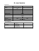
XL Laser Systems Specifications: Laser Power Field Size Z axis Overall dimensions Weight Max Speed Max Resolution Computer interface File storage Controls Power Cooling Z-Axis load Software compatibility XL-9200 See Laser Options 36”x24” (41.5”x29.5” max part) 8.5” motorized 56”w x 48”d x 48”t 500 lbs (without laser) 100 in/sec XL-12000 See Laser Options 48”x24” (53.5”x29.5” max part) 8.
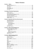
Table of Contents Section 1 - Safety Description of Appropriate Use ........................................................................................1-1 General Safety .................................................................................................................1-1 Laser Safety .....................................................................................................................1-2 Safety Labels ........................................................................
Section 1 Safety Description of Appropriate Use This device is designed for laser cutting and engraving of the materials listed in this manual, in a laboratory, workshop, or light duty manufacturing environment. Materials to be processed must fit completely inside the system for proper operation.
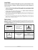
Laser Safety The device contains a sealed carbon dioxide (CO2) laser in a Class I enclosure that produces intense invisible and visible laser radiation at a wavelength of 10.6 microns in the infrared spectrum. For your protection, this enclosure is designed to completely contain the CO2 laser beam. Improper use of controls and adjustments, or performance of procedures other than those specified, may invalidate the safety of this system.
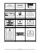
DANGER DANGER AVOID EXPOSURE INVISIBLE AND VISIBLE LASER RADIATION WHEN OPEN AVOID EYE OR SKIN EXPOSURE TO DIRECT OR SCATTERED RADIATION INVISIBLE LASER RADIATION IS EMITTED FROM THIS APERTURE 221-0017-0 221-0018-0 LASER DIODE WAVELENGTH: 630-680 nm MAX.
Section 1-4
Section 1-5
EU Compliance (CE) L A S E R S Y S T E M S I N C. Product Identification: XL9200/XL12000 Laser Engraving and Cutting Systems Manufacturer: Universal Laser Systems, Inc. 16008 N. 81st St. Scottsdale, AZ 85260 Phone: (480) 483-1214 Fax: (480) 483-5620 USA This equipment Is manufactured in conformity with the following directives: 89/336/EEC 73/23/EEC 98/37/EEC (EMC Directive) (Low Voltage Directive) (Machinery Directive) based on the standards listed.
FCC Compliance This ULS laser system has been tested and found to comply with Federal Communication Commission (FCC) directives regarding Electromagnetic Compatibility (EMC). In accordance with these directives ULS is required to provide the following information to its customers. FCC Compliance Statement and Warnings This device complied with FCC Rules Part 15. Operation is subject to the following two conditions: 1. This device may not cause harmful interference, and 2.
Section 2 System Installation The following operational guidelines are vital to a safe and productive environment. responsibility to provide a proper operating environment. It is your Damage to the laser system due to an inadequate or improper operating environment is considered abuse and WILL NOT be covered under warranty.
INSTALLATION • Level the feet by placing a bubble level across the top of the legs at position 1 and 2. Using a wrench, adjust the feet until the bubble is level. Do the same across the top of the rear legs at position 3 and 4. DO NOT adjust the legs between positions 3 and 1 and between positions 2 and 4. This adjustment has been pre-set at the factory and further adjustment may twist the body of the system. DO NOT REPLACE THE LEVELING FEET WITH CASTERS.
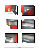
INSTALLATION Observe the “V” groove along the upper (3) and lower (2) part of the laser cartridge and the alignment plate (1) at the end. If you have purchased two lasers, mount the first cartridge onto the LOWER mounting blocks first. Single laser users should mount the laser in the top position. Before you can mount the lower laser, you MUST remove the red, beam tube plug. If removing the plug, simply grasp it by the sides and gently twist it clockwise and counterclockwise while pulling it towards you.
INSTALLATION Electrical Power Source • • • • • • The electrical power requirements can be found printed on the sticker next to the power inlet of the laser system. Noisy or unstable electricity as well as voltage spikes may cause interference and possible damage to the device’s electronics. If electrical power fluctuations, brown outs, or constant power outages are a problem in your area, an electrical power stabilizer, UPS (Uninterruptible Power Supply), or backup generator may be required.
INSTALLATION Computer and Operating System Minimum Computer Requirement • • • • • • • • Windows XP Home or Professional Edition computer. Macintosh computers are not compatible 1.
INSTALLATION When a software company updates their version of their programs, it can sometimes cause conflicts with our printer driver. Our programmers constantly test new software programs and updated versions for compatibility. We will update our printer driver to address issues that we have control of. For bugs or problems with your software not related to the laser system, please contact the software manufacturer. We recommend checking with the software manufacturer for the latest patches and revisions.
INSTALLATION 12. The next step is to set the default value for the line width and color when drawing graphic objects. To do this, click on the outline tool, then the outline pen dialog in the fly out. With “Graphic” being the only one selected, click “OK”. Click the down arrow in the Color dropdown box to expand the list and click on the color red. Click the down arrow in the “Width” dropdown box to expand the list and click “Hairline”. The units can be “Inches”, “millimeters” or anything else you prefer.
INSTALLATION 12. The next step is to set the default value for the line width and color when drawing graphic objects. To do this, click on the outline tool, then the outline pen dialog in the flyout. With “Graphic” being the only one selected, click “OK”. Click the down arrow in the Color dropdown box to expand the list and click on the color red. Click the down arrow in the “Width” dropdown box to expand the list and click “Hairline”. The units can be “Inches”, “millimeters” or anything else you prefer.
INSTALLATION Graphics Software Setup Choosing the right graphics software program to run the laser system is essential for maximum usage and control of the laser system. Not all software can be used to run the laser system because many have limitations. Because you may be using word processing software to output to your laser printer does not mean you should use it to output to your laser engraving system. Setting up you software correctly is essential to running the laser system properly.
INSTALLATION COLOR BLACK RED GREEN YELLOW BLUE MAGENTA CYAN ORANGE RED 0 255 0 255 0 255 0 255 GREEN 0 0 255 255 0 0 255 102 BLUE 0 0 0 0 255 255 255 0 If using a color other than the exact colors listed above, the driver will attempt to match it to a color in the driver that it most closely resembles. The driver will then use that color’s power setting and apply a halftone pattern to represent the original color’s shade.
INSTALLATION Overlapping Fills If the artwork created has overlapping filled areas, the driver will automatically filter these fills to prevent the overlapped area from being engraved twice. This is similar to color separation in the printing industry. The entire filled area of the object on top will be engraved and only the visible part of the underlying filled area will be engraved. The final result is a what-you-see-is-what-you-get output.
INSTALLATION Monochrome Bitmaps If you scan the image in monochrome (black and white) mode, set your scanner to at least 600 DPI. The higher the DPI, the smoother the image will be. Scanning monochrome images at 300 DPI is the minimum recommended resolution but scanning them at 600 DPI will provide a significant improvement in the image quality. Clean it up in your bitmap image-processing program and save it to your hard disk.
INSTALLATION Postscript (PS) Images The laser system is NOT a postscript device. This means that postscript fills, postscript textures, and especially POSTSCRIPT FONTS WILL NOT be able to print to the laser system. Sometimes using Adobe Type Manager (ATM) will allow some postscript fonts to print correctly but most of the time does not work properly.
Section 3 OPERATION AND PRINTER DRIVER CONTROLS System Operation Powering On the System To power on the system, first switch on the main circuit breaker located at the rear of the machine. This turns on the DC power supplies. Then, momentarily press the ON button located on the system control panel. The Control Panel The control panel of the laser system provides easy access to all of the controls necessary for cutting and engraving operations. 1. Emergency Stop 2. On / Off 3. File Name 4.
OPERATION AND PRINTER DRIVER CONTROLS Control Panel Functions Emergency Stop Depressing the Emergency Stop button instantly disconnects all AC power to the system. This button should only be used in case of emergency. To reset the system after executing an E-stop, twist the red button clockwise to release the button. Then, reset the main circuit breaker at the rear of the machine.
OPERATION AND PRINTER DRIVER CONTROLS The Menu System The Viewer Mode When first powered on, the system will initialize and the display will enter the Viewer Mode. In this mode, the display will automatically show the last file entered into memory. This indicates the system is ready for operation. The file name, the number of cycles executed (copies) and the execution time will be displayed in the Viewer mode.
OPERATION AND PRINTER DRIVER CONTROLS Air/ Gas Flow The air or gas flow rate can be set from 10% to 100%, in 10% increments. Image The Image Density set in the print driver is displayed, but cannot be edited. Which Laser Both / Top / Bottom Red Dot Pointer On / Off Delete This File Yes / No, used to delete selected file. System Options Menu About SW: Software Version Vx.xx FW: Firmware Version Vx.xx HW: Hardware Version Vx.
OPERATION AND PRINTER DRIVER CONTROLS Cutting Table (Optional) Installed Yes / No: Used for calibration of an optional cutting table. 1. Home Z axis. 2. Press to enter the motion menu. 3. Press again until Z axis is highlighted. to accept. 4. Press 5. SYSTEMS OPTIONS MENU will appear. 6. Scroll down to the CUTTING TABLE INSTALLED. to enter. 7. Press again to toggle CUTTING TABLE INSTALLED. 8. Press to accept. 9. Press too choose CALIBRATE. 10.
OPERATION AND PRINTER DRIVER CONTROLS Clear Cache Yes / No: Permanently deletes ALL stored jobs from system hard drive. Screen Saver Sets delay in screen saver on time. Align Camera (Optional) Used for calibrating offset from center of focus lens to center of camera. 1. Focus on material. 2. Press / / Align Camera / . 3. Place material in lower right corner. 4. Press OK, a cross hair will be engraved. DO NOT MOVE MATERIAL. 5. After cross hair appears scroll down to ALIGN CROSS HAIR, press . 6.
OPERATION AND PRINTER DRIVER CONTROLS Manual Motion When in the Viewer mode, the Manual Motion screen can be accessed by pressing the XY/Y button. Once opened, you can toggle between X-Y motion and Z- Motion. The selected axes can then be moved manually using the Direction Keys. Focusing the Laser The laser beam passes through the focus lens and converges to a small spot, called the focus point, approximately 2 inches from the bottom of the focus carriage when using a 2.0 lens.
OPERATION AND PRINTER DRIVER CONTROLS When using the Z Position method, it is best to first calibrate the Focus position of the focus lens installed. This will insure that the focus position is correct. To do this, open the System Options Menu, and select Home Z-axis. Make certain that there is nothing under the Z-table that could obstruct the table motion. Select XY/Z and use the Motion Control buttons to position the focus carriage to the focus tool.
OPERATION AND PRINTER DRIVER CONTROLS NOTE: When adjusting the printer driver settings, it is highly recommended that you practice engraving or cutting on a scrap portion of that material in case the settings need to be re-adjusted to obtain the desired results. Laser Settings Pen Mode The driver uses the word “PEN” because the laser system works similar to the operation of a pen plotter output device.
OPERATION AND PRINTER DRIVER CONTROLS % Power and % Speed work together in determining how deep the engraving or cutting will be. Higher power and slower speeds produce deeper results. Lower power and higher speeds produce shallower results. NOTE: 100% raster speed is different than 100% vector speed. Due to the inertia of the X-axis arm, movements in the Y-direction, the speed range is one-third raster speed. PPI Available settings are 1 to 1000.
OPERATION AND PRINTER DRIVER CONTROLS Image Density (DPI) settings will also have an effect on vector quality and vector speeds when vectoring other than straight horizontal or vertical lines. For example, a circle is made up of very small straight-line segments linked together at very small angles. If you choose a high quality setting such as 6 (1000 DPI), then these segments are as small as possible and they are high in quantity.
OPERATION AND PRINTER DRIVER CONTROLS 3D There are two ways to use this feature. The first method is used produce an engraving that has a contoured depth, giving it a three dimensional feel. It is used in combination with grayscale bitmaps by automatically assigning laser power levels to the shades of gray of the bitmap WITHOUT converting the image to a halftone. These power settings are based off the setting you entered for the color black, in the printer driver.
OPERATION AND PRINTER DRIVER CONTROLS The setting that produces the highest contrast using the least amount of %Power is called the nominal power setting. Defaults When you click this button, the ULS 3D Power Calibration screen will appear. Notice that there are 16 slider bars representing the 16 shades of gray of the calibration scale. The 00 and the 15 are not adjustable as they represent white and black. The 14 other ones can be adjusted.
OPERATION AND PRINTER DRIVER CONTROLS Defaults Selecting it brings up a pop-up window so you can choose from the following settings: Taper Selection Choose from various types of shoulder angles. Experiment with each setting and note the result. Invert Page This converts all black objects into white and all white objects into black for the ENTIRE PAGE. This is very useful for engraving a full sheet of rubber stamps. Mirror Page This mirrors the ENTIRE PAGE from left to right (horizontally).
OPERATION AND PRINTER DRIVER CONTROLS About Clicking Version will display a pop-up dialog box containing information on the current driver version number as well as the driver’s copyright notice. If contacting technical support, it is important to have the version number of your driver available. Print Direction Your choices are Down or Up. The default direction is Down which begins engraving at the top of the field and finishes at the bottom.
OPERATION AND PRINTER DRIVER CONTROLS Universal Laser Systems, Inc. Setting this parameter too low may cause the effective part of the graphic to appear thin, faint, fuzzy, or non-existent. Too high of a parameter will cause these objects to appear thicker, bolder, or more powered than the high density areas of the graphic. DENSITY: Adjusts the difference between the entire non engraved and engraved areas. If the parameter is too high, then the entire engraved image may appear thick, bold or over powered.
OPERATION AND PRINTER DRIVER CONTROLS Step 2: Using text to set the CONTRAST parameter. Type in a random line of text, using the Times New Roman font, set at 8 or 10 points in size. Make sure that the text string is at least 6 inches long and that the characters used include punctuation marks, spaces, and lower and upper case as in the following example: Universal Laser Systems, Inc.
OPERATION AND PRINTER DRIVER CONTROLS The Image Enhancement settings for that material are now complete. If you feel that you can “tweak” it a little more, go back to step 2 and try again, but this time start with your current Image Enhancement settings that you saved. It is not necessary to reset your nominal power setting and we recommend that you leave it the same as the value you determined in step 1.
OPERATION AND PRINTER DRIVER CONTROLS IMAGE DENSITY 6 5 4 3 2 ANGLE 45 DEGREES 45 DEGREES 45 DEGREES 45 DEGREES 45 DEGREES SHAPE ROUND ROUND ROUND ROUND ROUND LINES PER INCH 180 90 60 45 36 Error Diffusion Unlike halftoning, error diffusion scatters the black pixels in a random pattern to represent shading. It uses the quantity of black dots instead of the size of the black dots to represent the different shades of gray.
OPERATION AND PRINTER DRIVER CONTROLS SORT ONLY The printer driver collects all the vectors from the application software, stores them in temporary memory, sorts them, and the outputs them in the following order: • All open path vectors are output first (not closed path vectors like circles and squares) beginning with the end point of the vector path that is closest to the current position of the focus carriage.
Section 4 Basic Maintenance Keeping the laser system clean will ensure the highest quality engraving. The frequency of cleaning will depend entirely on the type of material being engraved, the performance of your exhaust system, the operating environment, and the amount of laser system usage over a given period of time. Dirt or debris that is allowed to build up on the motion system components will cause uneven or rough engraving, or loss of engraving position as well as premature component failure.
BASIC MAINTENANCE Optics A visual inspection of the #2 and #3 mirrors, beam window, and focus lens should be performed at least once a day. DO NOT clean an optic that is visually clean. Excessive cleaning can damage the optic. To prevent contamination, wash your hands thoroughly before cleaning any optic. NEVER touch any optic with your fingers. The acids from your skin can destroy the optical coatings.
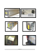
BASIC MAINTENANCE Beam Window Figure 5 Figure 6 The Beam Window is where the laser beam enters into the engraving area. It is located in the upper left hand corner of the engraving area against the back wall and is yellow in color. It is only necessary to clean the front side of the beam window. Do not remove the optic to clean it; simply clean it in the same manner as the #2 mirror. To clean you must remove the beam window diffuser by slightly rotating CCW until diffuser is free (Fig 5).
BASIC MAINTENANCE Y Guide Wheels Figure 8 The Y Axis contains 4 wheels, 2 located on top of the right Y Axis Rail and 2 below. To properly clean the Y Axis wheels, you must lower the Right Side Panel. 1st lower the Rear Laser Cover by disengaging both latches. Locate and remove both front and rear 3/32” Button Head Screws (Fig 8). The Right Side Panel is mounted using hinges, slowly lower cover.
BASIC MAINTENANCE Maintenance Schedule Since the maintenance requirements of the laser system is dependent on the type of material being run, the quantity of material being removed, the hours of operation, and the quality of the exhaust blower, it must be user defined.
BASIC MAINTENANCE ERROR Duplicate Address. End of Travel Detected. CAUSE SOLUTION IP address was entered that already exists on network. Caused by motion fault while the motors were de-energized. Contact System Administrator for alternative IP Address. Move the laser carriage by hand away from the side of the machine. Recycle power to the engraver. Motion will be enabled. 1) Inspect lens for presence of magnet(s).
Section 5 Material Settings Guide This section provides sample driver settings and helpful hints to get started engraving and/or cutting the materials listed. Safety NEVER LEAVE THE LASER SYSTEM RUNNING UNATTENDED FOR ANY REASON. Exposure to the laser beam can cause ignition of combustible materials. All laser cutting and engraving should be constantly supervised. NEVER OPERATE THE LASER SYSTEM WITHOUT A PROPERLY INSTALLED AND OPERATING EXHAUST SYSTEM.
MATERIAL SETTINGS GUIDE • Laser engraving or cutting materials other than those described in this manual can be a safety hazard and can damage the laser system. • Damages to the laser system due to neglect, misuse, or operator error ARE NOT covered under warranty. • Damage to the laser system due to an inadequate or improper operating environment is considered abuse and ARE NOT covered under warranty.
MATERIAL SETTINGS GUIDE NOTE When engraving very small objects, top speed cannot be achieved because acceleration and deceleration of the motion system requires time and distance. The laser system will automatically adjust itself to a maximum engraving speed that it can achieve due to the size and position of the graphic. This is why you might notice that there might be no difference in engraving time on certain graphics whether you choose 100% speed or less.
MATERIAL SETTINGS GUIDE ACRYLIC - CAST AND EXTRUDED LIGHT RASTER ENGRAVING LASER WATTAGE 25 30 35 40 45 50 55 60 POWER 53 44 38 34 30 27 24 22 SPEED 100 100 100 100 100 100 100 100 PPI 500 500 500 500 500 500 500 500 PASS 1 1 1 1 1 1 1 1 DEPTH .002” .002” .002” .002” .002” .002” .002” .002” DEEP RASTER ENGRAVING LASER WATTAGE 25 30 35 40 45 50 55 60 POWER 100 100 100 100 100 100 100 100 SPEED 60 64 68 73 77 81 86 90 PPI 500 500 500 500 500 500 500 500 PASS 1 1 1 1 1 1 1 1 DEPTH .010” .010” .
MATERIAL SETTINGS GUIDE COMMENTS There are two types of acrylic available, cast and extruded. Cast turns white or frosted and extruded remains clear when engraved. Use extruded acrylic for paint filled engraving and cast for regular engraving. Cast engraves better without masking. Lightly engrave the surface to frost it with a low power setting such as the first setting listed above.
MATERIAL SETTINGS GUIDE ACRYLIC - MIRRORED LIGHT RASTER ENGRAVING LASER WATTAGE 25 30 35 40 45 50 55 60 POWER 58 49 43 40 35 32 29 27 SPEED 100 100 100 100 100 100 100 100 PPI 500 500 500 500 500 500 500 500 PASS 1 1 1 1 1 1 1 1 DEPTH .003” .003” .003” .003” .003” .003” .003” .003” DEEP RASTER ENGRAVING LASER WATTAGE 25 30 35 40 45 50 55 60 POWER 100 100 100 100 100 100 100 100 SPEED 60 64 68 73 77 81 86 90 PPI 500 500 500 500 500 500 500 500 PASS 1 1 1 1 1 1 1 1 DEPTH .010” .010” .010” .010” .
MATERIAL SETTINGS GUIDE COMMENTS Engraving mirrored acrylic is similar to engraving regular acrylic. The idea is to engrave through the mirrored backing enough to begin to penetrate into the acrylic. Engraving deeply will cause a crusty residue to form just like with non-mirrored acrylic. A double image will appear if engraving on the front side of the mirror. It is not necessary to mask the backside when engraving because the mirrored backing shields the acrylic from smoke damage.
MATERIAL SETTINGS GUIDE ANODIZED ALUMINUM RASTER ENGRAVING LASER WATTAGE 25 30 35 40 45 50 55 60 POWER 72 60 52 45 40 36 32 30 SPEED 100 100 100 100 100 100 100 100 PPI 500 500 500 500 500 500 500 500 PASS 1 1 1 1 1 1 1 1 DEPTH .001” .001” .001” .001” .001” .001” .001” .001” VECTOR ENGRAVING LASER WATTAGE 25 30 35 40 45 50 55 60 POWER 12 10 9 8 7 6 5 4 SPEED 4.0 4.0 4.0 4.0 4.0 4.0 4.0 4.0 PPI 1000 1000 1000 1000 1000 1000 1000 1000 PASS 1 1 1 1 1 1 1 1 DEPTH .001” .001” .001” .001” .001” .
MATERIAL SETTINGS GUIDE BRASS - PAINTED RASTER ENGRAVING LASER WATTAGE 25 30 35 40 45 50 55 60 POWER 29 27 25 23 21 19 17 15 SPEED 100 100 100 100 100 100 100 100 PPI 500 500 500 500 500 500 500 500 PASS 1 1 1 1 1 1 1 1 DEPTH .001” .001” .001” .001” .001” .001” .001” .001” VECTOR ENGRAVING LASER WATTAGE 25 30 35 40 45 50 55 60 POWER 6 5 4 3 3 3 2 2 SPEED 4.0 4.0 4.0 4.0 4.0 4.0 4.0 4.0 PPI 1000 1000 1000 1000 1000 1000 1000 1000 PASS 1 1 1 1 1 1 1 1 DEPTH .001” .001” .001” .001” .001” .001” .
MATERIAL SETTINGS GUIDE CORIAN / AVONITE / FOUNTAINHEAD RASTER ENGRAVING LASER WATTAGE 25 30 35 40 45 50 55 60 POWER 100 100 100 100 100 100 100 100 SPEED 44 53 61 70 79 88 95 100 PPI 500 500 500 500 500 500 500 500 PASS 1 1 1 1 1 1 1 1 DEPTH .005” .005” .005” .005” .005” .005” .005” .005” DEEP RASTER ENGRAVING LASER WATTAGE 25 30 35 40 45 50 55 60 POWER 100 100 100 100 100 100 100 100 SPEED 13 15 18 20 23 26 28 30 PPI 1000 1000 1000 1000 1000 1000 1000 1000 PASS 1 1 1 1 1 1 1 1 DEPTH .015” .
MATERIAL SETTINGS GUIDE CORK RASTER ENGRAVING LASER WATTAGE 25 30 35 40 45 50 55 60 POWER 80 80 80 80 80 80 80 80 SPEED 38 45 52 60 67 75 84 90 PPI 500 500 500 500 500 500 500 500 PASS 1 1 1 1 1 1 1 1 DEPTH .010” .010” .010” .010” .010” .010” .010” .010” VECTOR ENGRAVING LASER WATTAGE 25 30 35 40 45 50 55 60 POWER 12 10 9 8 7 6 5 4 SPEED 4.0 4.0 4.0 4.0 4.0 4.0 4.0 4.0 PPI 500 500 500 500 500 500 500 500 PASS 1 1 1 1 1 1 1 1 DEPTH .010” .010” .010” .010” .010” .010” .010” .
MATERIAL SETTINGS GUIDE DELRIN RASTER ENGRAVING LASER WATTAGE 25 30 35 40 45 50 55 60 POWER 100 100 100 100 100 100 100 100 SPEED 22 26 30 35 39 44 48 52 PPI 500 500 500 500 500 500 500 500 PASS 1 1 1 1 1 1 1 1 DEPTH .015” .015” .015” .015” .015” .015” .015” .015” VECTOR CUTTING LASER WATTAGE 25 30 35 40 45 50 55 60 POWER 75 75 75 75 75 75 75 75 SPEED 2.0 2.4 2.8 3.2 3.6 4.0 4.4 4.8 PPI 200 200 200 200 200 200 200 200 PASS 1 1 1 1 1 1 1 1 DEPTH .060” .060” .060” .060” .060” .060” .060” .
MATERIAL SETTINGS GUIDE GLASS / CRYSTAL RASTER ENGRAVING LASER WATTAGE POWER 25 100 30 100 35 100 40 100 45 100 50 100 55 100 60 100 COMMENTS: Engrave at Image Density 4. VECTOR ENGRAVING LASER WATTAGE 25 30 35 40 45 50 55 60 POWER 10 10 10 10 10 10 10 10 SPEED 13 15 18 20 23 26 28 30 PPI 300 300 300 300 300 300 300 300 PASS 1 1 1 1 1 1 1 1 DEPTH .001 .001 .001 .001 .001 .001 .001 .001 SPEED 3.3 4.0 4.6 5.3 5.9 6.6 7.3 7.9 PPI 300 300 300 300 300 300 300 300 PASS 1 1 1 1 1 1 1 1 DEPTH .001 .001 .
MATERIAL SETTINGS GUIDE LEATHER RASTER ENGRAVING LASER WATTAGE 25 30 35 40 45 50 55 60 POWER 45 38 33 28 25 23 20 19 SPEED 100 100 100 100 100 100 100 100 PPI 500 500 500 500 500 500 500 500 PASS 1 1 1 1 1 1 1 1 DEPTH .001” .001” .001” .001” .001” .001” .001” .001” VECTOR ENGRAVING LASER WATTAGE 25 30 35 40 45 50 55 60 POWER 6 5 4 4 3 3 3 3 SPEED 4.0 4.0 4.0 4.0 4.0 4.0 4.0 4.0 PPI 500 500 500 500 500 500 500 500 PASS 1 1 1 1 1 1 1 1 DEPTH .001” .001” .001” .001” .001” .001” .001” .
MATERIAL SETTINGS GUIDE MARBLE RASTER ENGRAVING LASER WATTAGE 25 30 35 40 45 50 55 60 VECTOR ENGRAVING LASER WATTAGE 25 30 35 40 45 50 55 60 POWER 100 100 100 100 100 100 100 100 SPEED 35 42 48 55 62 69 77 82 PPI 500 500 500 500 500 500 500 500 PASS 1 1 1 1 1 1 1 1 DEPTH .003” .003” .003” .003” .003” .003” .003” .003” POWER 24 20 17 15 13 12 SPEED 4.0 4.0 4.0 4.0 4.0 4.0 4.0 4.0 PPI 500 500 500 500 500 500 500 500 PASS 1 1 1 1 1 1 1 1 DEPTH .003” .003” .003” .003” .003” .003” .003” .
MATERIAL SETTINGS GUIDE MAT BOARD RASTER ENGRAVING LASER WATTAGE 25 30 35 40 45 50 55 60 POWER 72 60 52 45 40 36 32 30 SPEED 80 80 80 80 80 80 80 80 PPI 250 250 250 250 250 250 250 250 PASS 1 1 1 1 1 1 1 1 DEPTH .005” .005” .005” .005” .005” .005” .005” .005” VECTOR ENGRAVING LASER WATTAGE 25 30 35 40 45 50 55 60 POWER 24 20 17 15 13 12 11 10 SPEED 4.0 4.0 4.0 4.0 4.0 4.0 4.0 4.0 PPI 250 250 250 250 250 250 250 250 PASS 1 1 1 1 1 1 1 1 DEPTH .005” .005” .005” .005” .005” .005” .005” .
MATERIAL SETTINGS GUIDE MELAMINE - STANDARD ENGRAVING LIGHT RASTER ENGRAVING LASER WATTAGE 25 30 35 40 45 50 55 60 POWER 100 100 100 100 100 100 100 100 SPEED 25 30 34 39 44 50 55 59 PPI 500 500 500 500 500 500 500 500 PASS 1 1 1 1 1 1 1 1 DEPTH .015” .015” .015” .015” .015” .015” .015” .015” DEEP RASTER ENGRAVING LASER WATTAGE 25 30 35 40 45 50 55 60 POWER 100 100 100 100 100 100 100 100 SPEED 17 21 24 27 31 35 38 41 PPI 500 500 500 500 500 500 500 500 PASS 1 1 1 1 1 1 1 1 DEPTH .020” .020” .
MATERIAL SETTINGS GUIDE MELAMINE - PHOTO/CLIPART ENGRAVING RASTER ENGRAVING LASER WATTAGE POWER SPEED 25 80 38 30 80 45 35 80 52 40 80 60 45 80 67 50 80 75 55 80 84 60 80 90 COMMENTS: Engrave unmasked. Use an Image Density of 5. PPI 500 500 500 500 500 500 500 500 PASS 1 1 1 1 1 1 1 1 DEPTH .008” .008” .008” .008” .008” .008” .008” .008” RASTER ENGRAVING LASER WATTAGE POWER SPEED 25 80 25 30 80 30 35 80 35 40 80 40 45 80 45 50 80 50 55 80 56 60 80 60 COMMENTS: Engrave unmasked.
MATERIAL SETTINGS GUIDE PLASTIC - ENGRAVERS MICROSURFACED RASTER ENGRAVING LASER WATTAGE 25 30 35 40 45 50 55 60 POWER 29 27 25 23 21 19 17 15 SPEED 100 100 100 100 100 100 100 100 PPI 500 500 500 500 500 500 500 500 PASS 1 1 1 1 1 1 1 1 DEPTH .001” .001” .001” .001” .001” .001” .001” .001” VECTOR CUTTING LASER WATTAGE 25 30 35 40 45 50 55 60 POWER 60 50 43 38 34 30 27 25 SPEED 1.2 1.2 1.2 1.2 1.2 1.2 1.2 1.2 PPI 150 150 150 150 150 150 150 150 PASS 1 1 1 1 1 1 1 1 DEPTH .060” .060” .060” .
MATERIAL SETTINGS GUIDE RUBBER STAMPS RASTER ENGRAVING LASER WATTAGE 25 30 35 40 45 50 55 60 POWER 100 100 100 100 100 100 100 100 SPEED 10 12 14 16 17 20 22 23 PPI 500 500 500 500 500 500 500 500 PASS 1 1 1 1 1 1 1 1 DEPTH .030” .030” .030” .030” .030” .030” .030” .030” PERFORATED VECTOR CUTTING LASER WATTAGE 25 30 35 40 45 50 55 60 POWER 60 60 60 60 60 60 60 60 SPEED 1.3 1.6 1.8 2.1 2.3 2.6 2.9 3.1 PPI 90 90 90 90 90 90 90 90 PASS 1 1 1 1 1 1 1 1 DEPTH .040” .040” .040” .040” .040” .040” .
MATERIAL SETTINGS GUIDE SIGN VINYL RASTER ENGRAVING LASER WATTAGE 25 30 35 40 45 50 55 60 POWER 100 100 100 100 100 100 100 100 SPEED 19 23 26 30 34 38 42 45 PPI 500 500 500 500 500 500 500 500 PASS 1 1 1 1 1 1 1 1 DEPTH .015” .015” .015” .015” .015” .015” .015” .015” VECTOR CUTTING (KISS CUT) LASER WATTAGE 25 30 35 40 45 50 55 60 POWER 5 5 5 5 5 5 5 5 SPEED 3.3 4.0 4.7 5.3 6.0 6.7 7.4 8.1 PPI 500 500 500 500 500 500 500 500 PASS 1 1 1 1 1 1 1 1 DEPTH .003” .003” .003” .003” .003” .003” .003” .
MATERIAL SETTINGS GUIDE WOOD RASTER ENGRAVING LASER WATTAGE 25 30 35 40 45 50 55 60 POWER 100 100 100 100 100 100 100 100 SPEED 25 30 34 39 44 50 55 59 PPI 500 500 500 500 500 500 500 500 PASS 1 1 1 1 1 1 1 1 DEPTH .020” .020” .020” .020” .020” .020” .020” .020” VECTOR ENGRAVING LASER WATTAGE 25 30 35 40 45 50 55 60 POWER 80 80 80 80 80 80 80 80 SPEED 4.2 5.0 5.9 6.7 7.6 8.4 9.2 10.1 PPI 500 500 500 500 500 500 500 500 PASS 1 1 1 1 1 1 1 1 DEPTH .030” .030” .030” .030” .030” .030” .030” .
MATERIAL SETTINGS GUIDE Elevating the wood also helps to determine whether the laser has passed completely through since the cut pieces will fall through to the table when cutting is finished. Also, set up the drawing so that the inner pieces of the drawing are cut first, otherwise pieces may fall through at the wrong time. Not all wood finishes are created equal. When ordering wood from a supplier, be sure to specify that it is being used for laser engraving.