
Specifications
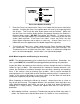
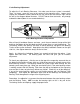

X-axis Bearing Adjustment
As the X-axis B reduction in the quality of the image that
the laser produces because the Focus Carriage will rock back and forth as it reverses
irection.
The
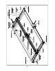
qua (2) Lockdown Screws
s the diagram indica es. Loosening the Lockdown Screws will allow the Tensioning
Springs at the top of the X-axis Bearing Tensioning Bracket to push the bracket
downwards. This downward push actually squeezes all three(3) bearings together to
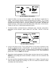
remove the clearance created by bearing wear. In other words, the bearings will self
adjust when the Lockdown Screws are simply loosened (about ¼ to ½ turn
counterclockwise). Now re-tighten the Lockdown Screws,. Do not tighten them too
tight, just snug enough to hold the X-axis Bearing Tensioning Bracket in place. If you
tighten the Lockdown Screw et might twist and cause an
correct adjustment. The objective is to remove the clearance between the outer
earing surface and the bearing tracks, NOT to make the bearings tight. This is why
nt of force to remove the
learance.
earings wear, there could be a
d
X-axis Bearing Clearance can be adjusted to remove the looseness and restore
lity. To do this, turn the laser system off and loosen the two
ta
s too tight the Tensioning Brack
in
b
we let the Tensioning Springs supply just a small amou
c
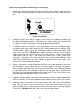
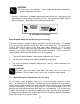
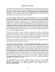
After making the adjustment, check to see if there is any more play in the Focus
Carriage by grasping it and gently trying to rotate it in a clockwise and counterclockwise
direction. If there is still clearance, repeat the procedure. It sometimes helps to move
the Focus Carriage left and right a few times while the Lockdown Screws are loose to
help settle the bearings in the bearing tracks.
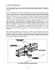
X-axis Bearing Clearance Adjustment
88