
Specifications

If using the “SERIAL” port, select the fastest possible “BAUD” rate for communication
since this effects how quickly the computer can send files to the laser system. For
“BAUD” rates of “9600” and above, set the number of “STOP BITS” on the computer to
a higher value than the number of “STOP BITS” selected on the laser system. For
example if the number of “STOP BITS” on the laser system is set to “1”, then set the
computer’s stop bits to “1.5” or “2”.
“PARITY” of the laser system and the computer MUST match exactly and the choices
are “ODD”, “EVEN”, or “NONE”. Pressing the “SELECT” button while the cursor is on
“PARITY” will toggle through these choices.
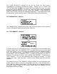
The “SET ROTARY AXIS” submenu
The Rotary Fixture Axis is a setting that is pre-set at the factory. The laser system will
sense when the Rotary Fixture is plugged in and will position the X-Axis arm directly
over the centerline of rotation automatically when it begins to engrave. This setting can
be altered if you position the Rotary Fixture in a location OTHER than the pre-drilled
screw holes on the engraving table.
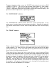
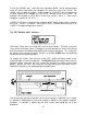
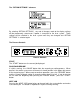
To change this setting, turn the laser system OFF, place the Rotary fixture on the
engraving table in the desired position, and DO NOT plug the Rotary Fixture into the
electrical socket. Now turn the laser system ON and with the motion system arrow
buttons, position the X-Axis arm’s focal lens carriage directly over the Rotary Fixture’s
centerline of rotation as the following diagram demonstrates:
The left and right position (X-position) of the focus carriage is irrelevant in this setting.
It’s position is determined by where the graphic is placed in the graphics program,
therefore, it’s position is ignored by the laser system and cannot be set in this
procedure.
47