
Specifications


red, green, yellow, blue, magenta, cyan, and orange. Some programs will provide
these basic colors pre-defined and other programs may require the creation of each of
the colors by defining them in CMYK percentages. If the eight driver colors are not
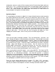
automatically provided in the software, use the chart below to create the eight driver
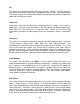
colors by specifying the appropriate CMYK values:
COLOR CYAN MAGENTA YELLOW BLACK
BLACK
0 % 0 % 0 % 100 %
RED
0 % 100 % 100 % 0 %
GREEN
100 % 0 % 100 % 0 %
YELLOW
0 % 0 % 100 % 0 %
BLUE
100 % 100 % 0 % 0 %
MAGENTA
0 % 100 % 0 % 0 %
CYAN
100 % 0 % 0 % 0 %
ORANGE
0 % 60 % 100 % 0 %
If using a color other than the exact colors listed above, the driver will attempt to match
it to a color in the driver that it most closely resembles. The driver will then use that
color’s power setting and apply a halftone pattern to represent the original color’s
shade. For example, if using a color like pink to fill a rectangle, the driver takes a
reading of the percentage of different colors used to create that color and will use the
power setting assigned to one of the eight colors of the driver that it most closely
resembles. It might be expected that the driver will use the power setting assigned to
the color red but instead the driver may choose the magenta setting and halftone the
rectangle as a representation of the pink color’s lighter shade. To prevent the incorrect
assignment of laser power, be sure to use the right colors. If using graphics with colors
other than the eight listed above or to simplify the assignment of power settings, try
using the B/W Raster feature in the driver. This feature will cause the system to only
use the power setting assigned to the color black and halftone all of the other colors.
Outlines and Fills
The ULS Printer Driver distinguishes between raster mode (engraving) and vector mode
(cutting) by the type of graphic artwork being used. Basically all graphics other than
outlines of very thin line widths will be interpreted as engraved images and the raster
mode will be used for output. If laser cutting is desired, set the line thickness of the
lines that are drawn in the graphics software to .001 inches (.1 mm) or the smallest
possible line thickness that is available. The printer driver will interpret these objects as
vectors and will cut them out. The use of color fills or bitmaps will cause the laser
system to engrave. The combination of engraving and cutting is available in most
graphics software. We suggest that when combining engraving and cutting objects,
use different colors for the fills and outlines since engraving requires different power
settings than cutting objects. One thing to keep in mind when creating cutting objects is
that if the outline thickness is set too thick, the driver might interpret the outline as a
filled object and will engrave the outline instead of cutting. This might be desirable if
engraving thick outlines is necessary. The outline thickness at which the driver will
24