OPERATION MANUAL ULS-25E LASER SYSTEM INTERNATIONAL EDITION Universal Laser Systems, Inc. 16008 North 81st Street Scottsdale, AZ 85260 Phone: 602-483-1214 Fax: 602-483-5620 Volume I, Rev.
This publication and its contents are proprietary to Universal Laser Systems Inc., and are intended solely for the contractual use of Universal Laser Systems Inc. customers. This publication and its contents may not be reproduced or distributed for any other purpose without the written permission of Universal Laser Systems Inc. © Universal Laser Systems Inc., 1996 All Rights Reserved Notice Universal Laser Systems Inc.
Table of Contents Section 1 - Safety 1.1 Laser Safety............................................................................................. 5 1.2 Safety Labels ........................................................................................... 6 1.3 The Safety Interlock System .................................................................... 7 1.4 EMI Compliance ...................................................................................... 8 Section 2 - Installation 2.
Introduction The ULS-25E is designed to combine flexibility and full featured performance with simplicity and ease of use. Using advanced engineering and design, the ULS-25E offers finer control, higher precision, more versatility, better resolution, faster speed, and overall greater quality than any other laser system in its class.
Section 1 - Safety 1.1 Laser Safety The laser system contains a sealed carbon dioxide laser that produces intense and invisible laser radiation (at a wavelength of 10.6 microns in the infrared spectrum). The laser system is designed as a CLASS I device, meaning that the system is equipped with a protective housing and safety devices to completely contain the laser under normal use.
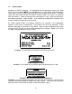
1.2 Safety Labels According to CDRH standards, all interlocked and non-interlocked covers that allow access to a laser beam MUST have appropriate laser safety labels attached to them. These labels must be visible to personnel prior to the removal of the covers. Additional labels must be installed inside the machine and be visible if the covers are removed from the machine.
Exposure Warning Label Location: To the right of the beam window inside the system where the laser beam enters the work area. On the laser mounting bracket before the first mirror and next to the aperture where the beam exits the laser tube. Warning Label for Non-interlocked Panels Location: On the inside and outside of the first mirror cover (visible when the fan cover is removed). 1.
1.4 EMI Compliance This ULS laser system has been tested and found to comply with both Federal Communication Commission (FCC) and European Union (EU) directives regarding Electromagnetic Compatibility (EMC). In accordance with these directives ULS is required to provide the following information to its customers. FCC Compliance Statement and Warnings This device Complied with FCC Rules Part 15. Operation is subject to the following two conditions: 1. This device may not cause harmful interference, and 2.
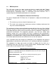
Section 2 - Installation 2.1 Unpacking and Assembling the Laser System The laser system is shipped in one crate that contains the system, a cart with casters and various accessories. The following steps outline the unpacking and assembly of the system. Please follow these steps carefully. IMPORTANT Save the shipping crate. If the system must be returned for service, it will have to be packed in its original shipping crate. 1. Unscrew and remove the top portion of the crate.
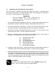
Cart Assembly 7. Engage the front caster lock downs to prevent the stand from rolling when placing laser system on it. Gently lift the laser system from the crate and place it on the cart.
8. Using the larger Allen wrench, attach the system to the cart using the four 1/4-20 Allen head screws and flat washers. The screws pass through the cart legs and into the bottom of the system as shown. 9. Once all of the screws are tight, adjust the thin nut on each of the casters so that all four wheels are touching the ground evenly. If desired, use a level gauge placed on the engraving table and adjust the casters until the laser system is completely level.
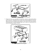
2.3 Exhaust System Requirements To properly exhaust fumes and smoke from the laser engraving system during operation, it is necessary to provide an exhaust unit moving a minimum of 235 CFM at 6 inches of static pressure. Many industrial supply companies carry blowers that should meet these requirements. THROUGH OUR RESEARCH WE HAVE ESTABLISHED GUIDELINES ON THE PROPER CFM RATINGS REQUIRED FOR THE EXHAUST SYSTEM.
Sample Exhaust System Layouts 13
2.4 Computer Recommendations and Setup The following computer configuration is the minimum requirement necessary to operate in the Windows environment. Using a computer with more speed, memory and storage capacity will enable the graphic images to be produced faster. A faster computer will perform calculations quicker and will shorten download time to the laser.
2.5 Laser System Installation CAUTION: Please make the following connections in the exact order described otherwise static electricity can damage the computer and/or the laser system’s electronics. 1. Connect the laser system’s power cord to a good quality surge suppresser and then the surge suppresser to a grounded outlet. Do the same for the computer system. 2.
Printers Dialog Box 3. Click on the “Add” button if other drivers are present in the “Installed Printers” dialog box. 4. Click on “Install Unlisted or Updated Printer” and click on “Install”. Add Unlisted Printers Dialog Box 5. The “Install Driver” dialog box will appear asking for the location of the new driver. 6. Insert the floppy disk containing the ULS Printer Driver into the appropriate disk drive and type in the correct drive letter. 7.
Add Unlisted or Updated Printer Dialog Box 8. Select the ULS-25E from the list and click on the “OK” button. The driver will now install itself to your c:\windows\system directory and the ULS-25E will appear in the “Installed Printers” section of the “Printers” dialog box. Printers Dialog Box 9. Select the ULS-25E and click on “Connect” if connecting to a port other than LPT1. Now select the appropriate port.
Connect Dialog Box 10. Click on “OK” and the “Printers” dialog box will re-appear. Printers Dialog Box 11. Selecting “Set As Default Printer” and “Use Print Manager” are of personal preference. Refer to the Windows manual on how to use Print Manager, if desired. We recommend that you do not use Print Manager because it serves no use to the laser system and it can become a nuisance. 12. Now you MUST click on “Setup” to initiate the installation of the driver.
Driver Settings Dialog Box 13. How to adjust the settings will be covered in a later chapter. Now you MUST click on “OK” in order for the driver to create a file called “Laser.ini” which the driver will install to your c:\windows directory. This file stores all of the driver settings as you change them. If you do not perform this procedure, any settings that get changed later on will not be stored in when the computer gets shut down.
4. Double-click on the “Add Printer” icon. 5. When the “Add Printer Wizard” appears click “Next”. 6. Select “Local Printer” and click “Next”. 7. When the “Manufacturer” and “Printers” menu list appears click “Have Disk” (Do not look for the printer in the menu). 8. Insert the driver disk. 9. Make sure the dialog box matches the floppy drive you are using: “A:\” or “B:\”. 10. Click on “OK”. 11. When the list of “Printers” appears choose “ULS-25E”. 12. Click on “Next”. 13.
1. Turn on your Macintosh computer and insert the ULS Macintosh driver disk in the computer’s disk drive. 2. Copy the ULS-25E and Engrave Monitor onto your Macintosh computer by dragging these items from the floppy disk folder into the “Extensions” folder located inside the “System” folder on your computers hard drive. 3.
Section 3 - Software Setup and Operation 3.1 Using Graphics Software Page Setup To properly generate and position artwork, most graphics software will permit the customization of the page size and orientation. Set the page orientation, in the graphics software to Landscape, and the page size to a horizontal length of 24 inches(609.6 mm) and vertical height of 12 inches(304.8 mm).
red, green, yellow, blue, magenta, cyan, and orange. Some programs will provide these basic colors pre-defined and other programs may require the creation of each of the colors by defining them in CMYK percentages.
interpret cut lines as filled objects is dependent on the software used. Usually, any line thickness .008 inches (.2 mm) or greater will engrave. The only way to determine the cross over point for line thickness is to experiment with different line widths. Software programs that do not have outline capabilities will not have the ability to cut. Image Processing Order When cutting or engraving a graphic image, the laser system will perform all engraving first, then proceed to cutting.
underneath, the laser system will then engrave out the fill and cut the hidden outline on top of the fill. This is a common occurrence when using pre-drawn ClipArt designed for laser printers. To prevent this from happening, turn on the B/W Raster feature in the driver. This feature disables the cutting mode and converts all visible outlines to engraved objects and ignores all hidden outlines.
graphics software. Some basic functions such as cropping, scaling, or mirroring might be possible but it is usually necessary to use an image processing software to perform a dot by dot editing or rotation of the bitmap. Monochrome bitmaps are engraved in the same manner as black filled text. The black area will turn the laser on and the white area turns the laser off. In order to engrave a photograph however, a halftone pattern must be created. A halftone is a series of dots arranged in a specific pattern.
Working with Fonts in the Windows Environment We recommend the use of True Type fonts with the laser system. TrueType fonts are the most versatile and should be used whenever possible. They provide the best print quality and will print well at any size. Other types of fonts might not print correctly to the laser system. Post Script fonts will not print correctly on the laser system unless you have the Adobe Type Manager (ATM) installed.
will highlight the color and allow changing of the settings by using the scroll bars or highlighting out and typing in each setting. It is possible to set one color at a time or click on additional colors to set more than one at a time. Power Setting Laser power is controlled by assigning the percentage of power from 0 - 100% to each color used in the graphic drawing. Since the laser is proportionally pulsed, this percentage represents how long the laser remains on for each laser pulse fired.
Set This button must be pressed after adjusting the Power, Speed, and PPI settings in order for these changes to take effect. If forgetting to click on “Set”, and clicking on the “OK” button instead, the settings will go back to the previous ones and will engrave the object with the incorrect settings. Advanced Turning this switch ON will permit the changing of the PPI settings. If the switch is turned OFF, the word “Auto” will appear in the PPI column and will be colored gray.
different shades of gray. The laser system represents different shades of gray by producing a halftone pattern when engraving. The halftone pattern is based upon the Resolution setting of the driver the same way grayscale bitmaps are interpreted. Refer to the chart on page 25 for specific details. Since ClipArt images use a wide variety of colors, shades, and outlines, the only effective way of engraving these images is to have this switch turned ON.
Help Select this option to access Help on the use of the ULS Printer Driver. Selecting “Help” and then “About” will display the current driver version number and our copyright notice. 3.3 Using DOS Based Programs When using DOS based programs, there are a few things to keep in mind. DOS software is not standardized and each application will work differently.
7. Power setting for plotter pens can only be done at the laser system itself through the main control panel display. Section 4.2 of this manual will explain how to set the Power, Speed, and PPI settings for plotter pens. It will also describe how to insert an “End of File” marker and why it is necessary after every file download. Please refer to that section for more explicit details. If having trouble with using DOS based programs, please contact our technical support. 3.
The Engrave Monitor Engrave Monitor The Engrave Monitor provides a graphical preview of the printed image and allows you to send the image to the printer or cancel printing at any time during the process by selecting the cancel button. While the image is being printed a pointer travels down the length of the page indicating printing progress and a counter indicates how many bytes of information have been sent. You can also pause printing by selecting the pause button and then resume printing at any time.
Working with Fonts in the Macintosh Environment We recommend the use of True Type Fonts. TrueType fonts are the most versatile and should be used whenever possible. They provide the best print quality and will print well at any size. Post Script fonts will not print correctly on the laser system unless your Macintosh has the Adobe Type Manager (ATM) extension loaded.
Section 4 - Laser System Operation 4.1 General System Overview 1. 2. 3. 4. 5. 6. 7. Top Door Top Door Window Top Door Gas Assist Shocks Exhaust Plenum Opening Motion System X-Axis Arm Engraving Table Focus Lens Holder Assembly 8. Rotary Fixture Socket 9. Front Door 10. Fan Enclosure 11. Z-Axis Adjustment Knob 12. Interlock Defeat Tool Socket 13. Control Panel 14.
4.2 The Control Panel Control Panel The control panel on the laser system provides easy access to all of the controls necessary for cutting and engraving operations. The control panel consists of a liquid crystal display (LCD), indicator lights, and selection buttons. The following sections will describe, in detail, how to get around in the menu control system and the significance of each item in the control panel.
Menu Control System Flow Chart 39
The “OPERATIONS DISPLAY” submenu As soon as the first job that is sent from the computer to the laser system is in the laser system’s buffer, the “OPERATIONS DISPLAY” submenu will appear displaying the job’s filename and associated power settings the were set in the ULS Printer Driver. This is the “OPERATIONS DISPLAY” submenu which will probably remain on most of the time during normal operation.
To access the “MAIN MENU” from the “OPERATIONS DISPLAY” submenu, pressing the “ESCAPE” button until it appears on the display. keep The “MAIN MENU” The “MAIN MENU” is the menu that allows access to all other submenus. The “BUFFER CONTROL” submenu Then The laser system comes standard equipped with an intelligent memory buffer that has built-in file compression.
the cursor to the right, then use the arrow buttons to move backward or forward through the list until the job desired is displayed and then press the “SELECT” button again. Eventually the buffer will fill up with jobs that will need to be removed from memory. It is possible to select each individual job and delete them one at a time. To accomplish this, make the desired job for deletion the current job in the same manner as previously described, then select the “DELETE THE FILE” option from the menu.
exceeds the remaining free buffer space. When this occurs, chances are that the EOF never made it to the buffer and the buffer will show that it is empty or that the job does not exist. If this happens, part of the job might still remain in the buffer and that part might become mixed up with other jobs. This is when having an “INSERT-END-OFFILE” option becomes important.
To access the power settings, press the “SELECT” button when the cursor is on DOS “POWER SETTINGS”, then use the up and down arrow buttons to scroll through settings 1 through 8. When the desired power setting number is found, press the “SELECT” button again to bring the cursor over to the left hand side of the display, and proceed to make the adjustments as previously described The “PREFERENCES” submenu The “PREFERENCES” submenu choice allows laser system reconfiguration.
Since every laser has its own personality, Tickle is adjustable through the control panel on the laser system. Tickle is set for each individual laser at the factory, but from time to time, the Tickle setting may need to be adjusted as the internal characteristics of the laser change over several months or several years of operation. Adjustments need only to be done if necessary. There are two main symptoms of a laser that needs Tickle adjustment.
too high, reduce the Rate setting, while observing the file as it is running, until the shadows disappear. If the Rate setting gets down to zero and the shadows are still present, then put the Rate back to its original number and reduce the Width by one. If the shadows still appear, keep reducing the Rate again until it does disappear. If the setting is too low, increase the Rate setting until the shadows appear, then back it off one or two numbers.
If using the “SERIAL” port, select the fastest possible “BAUD” rate for communication since this effects how quickly the computer can send files to the laser system. For “BAUD” rates of “9600” and above, set the number of “STOP BITS” on the computer to a higher value than the number of “STOP BITS” selected on the laser system. For example if the number of “STOP BITS” on the laser system is set to “1”, then set the computer’s stop bits to “1.5” or “2”.
Now, select the “YES SAVE Y AXIS” choice. If you change your mind and do not wish to alter the “ROTARY AXIS” position, select “CANCEL” instead and the original settings will be restored. NOTE: To save this setting in the laser systems memory configuration, “RETAIN SETTINGS” must be performed. This procedure is defined later in this section. If you do not “RETAIN SETTINGS”, all changes that you made, even after selecting “YES SAVE Y AXIS”, will be lost and the previous settings will remain.
The “LOAD DEFAULTS” selection on the last line resets the laser systems motherboard to its originally manufactured settings. Settings such as “TICKLE” and “SET ROTARY AXIS” will NOT be restored to the same settings that were in the laser system when you first received it. Chances are, these two settings were altered by the production department before the laser system was shipped. “LOAD DEFAULTS’ nullifies those settings made by our production department.
The “RETAIN SETTINGS” submenu Then By selecting “RETAIN SETTINGS”, any and all changes made to the display settings will be permanently stored even if power is turned off to the laser system. Those settings will be retained in the laser system until they are changed and “RETAIN SETTINGS” is selected again. The Process Controls Process Controls START The “START” button runs the current job displayed. PAUSE AND RESUME If a job is running, the “PAUSE” button halts the engraving or cutting process.
STANDBY Then The “STANDBY” button allows the laser system to shut down the power to the laser tube and the cooling fans. This is very useful when the user wants to shut down the laser system without losing the files in the memory buffer. To activate the “STANDBY” mode, press the “STANDBY” button and the bring the cursor down to the “YES, ACCEPT” line and press “SELECT”. Files can be downloaded to the laser system while in the “STANDBY” mode.
The Motion Control System The motion control section of the control panel (the four directional arrow buttons) enables the user to manually control motion system movement. Pressing and holding down an arrow button will cause the focus lens holder assembly to move in the respective direction. Pressing two adjacent arrow buttons will move the assembly in a diagonal direction. This part of the control panel is primarily used for focusing the laser beam on the engraving material using the focus tool.
In order to cut and engrave with precision the laser beam in the laser engraving system is focused to a small spot by the focus lens. There are two types of Z-Axis engraving table controls, manual (standard) and electric (optional). Manual To focus using the manual Z-axis Adjustment Knob, open the top door. Load your material into the upper left hand corner of the engraving table up against the rulers.
Electric (optional) To focus using the electric Z-axis table adjustment, open the top door. Load your material into the upper left hand corner of the engraving table up against the rulers. Now press the “SETUP” button and the focus lens holder assembly will move into the upper left hand corner of the engraving table right over your material. If the focus lens is not directly over your material, reposition it by using the motion control arrow buttons.
Step 3 Press the “SETUP” button and by using the motion control buttons, position the focus lens assembly over the engraving material. Adjust focus by using the focusing tool and adjusting the height of the engraving table. Step 4 Create a graphic using the graphics software program and position the graphic on screen so that it matches the placement of the object in the laser system. Step 5 Before printing, go to the ULS Printer Driver and assign the power settings.
fixture is square to the engraving area. The rulers also provide a visual guide as to where to locate the graphic in the graphics software. Tighten the thumbscrews. Installed Rotary Fixture 3. Next, connect the Rotary Fixture control cable to the receptacle on the laser engraving system. If necessary, refer to the diagram at the beginning of this chapter for the receptacle’s location. 4.
the centerline of the Rotary Fixture automatically. Now focus on the glass by using the focus tool and adjusting the table up or down. If the glass slopes too much in the engraving area, the Rotary Fixture can be tilted upwards to make the surface of the glass parallel with the motion system. To do this, lift up the left end of the fixture and place some sort of spacer underneath the fixture to prop it up.
4. Position the graphic, on screen, so that it will fit vertically within the new page height and horizontally within the engraving area of the glass. If the graphic does not fit within the vertical page size limits, the portion that is outside the page limit will not engrave. Remember, the new page size that the driver calculates from the diameter of the glass is it’s actual circumference. From the top of the page down to the bottom is one complete revolution of the glass.
9. Experiment with some scrap materials to determine where the graphic will engrave when the graphic is located in different areas on screen. 10. Set the driver parameters, send the file to print, and begin engraving. Operation of the Rotary Fixture in the Portrait mode 1. The Rotary Fixture can also operate in the Portrait mode providing that the engraving object is not too heavy. The Portrait mode will cause the Rotary Fixture to spin the object back and forth very quickly.
NOTE: Remember that the new page size that was established by the driver when the objects diameter was entered in indicates the circumference or distance around the outside of the object. Be sure to go back and adjust the graphics programs page size to match these new dimensions EXACTLY otherwise the graphic will engrave in the wrong place, engrave only partially, or not engrave at all.
4.7 Start Up Parameters for Various Materials This section provides driver settings and helpful hints to get started engraving and/or cutting various materials. These settings are to serve as a starting point and are not necessarily optimized for each particular application.
ACRYLIC - CAST AND EXTRUDED TYPE LIGHT RASTER ENGRAVING POWER 25 SPEED 100 PPI 500 PASS 1 DEPTH .001” COMMENTS: Remove original factory masking from the engraving surface. Leave the masking on the non-engraved surface to prevent accidental scratches. TYPE DEEP RASTER ENGRAVING POWER 100 SPEED 70 PPI 500 PASS 1 DEPTH .010” COMMENTS: This sample engraved deeper than the first sample. Engrave through original masking. Engraving too deep will lose detail. TYPE VECTOR ENGRAVING POWER 5 SPEED 4.
ADDITIONAL COMMENTS There are two types of acrylic available, cast and extruded. Cast turns white or frosted and extruded remains clear when engraved. Use extruded acrylic for paint filled engraving and cast for regular engraving. Cast engraves better without masking. Lightly engrave the surface to frost it with a low power setting such as the first setting listed above.
ACRYLIC - MIRRORED TYPE LIGHT RASTER ENGRAVING POWER 30 SPEED 100 PPI 500 PASS 1 DEPTH .003” COMMENTS: Engrave unmasked and on the backside in reverse text. Engraving on the front side of mirrored acrylic will visually produce a double image. TYPE DEEP RASTER ENGRAVING POWER 100 SPEED 70 PPI 500 PASS 1 DEPTH .010” COMMENTS: Masking is not necessary because the acrylic is protected from smoke damage by the mirrored backing. TYPE VECTOR ENGRAVING POWER 5 SPEED 4.0 PPI 500 PASS 1 DEPTH .
ADDITIONAL COMMENTS Engraving mirrored acrylic is similar to engraving regular acrylic. The idea is to engrave through the mirrored backing enough to begin to penetrate into the acrylic. Engraving deeply will cause, a crusty residue to form just like with non-mirrored acrylic. A double image will appear if engraving on the front side of the mirror. It is not necessary to mask the backside when engraving because the mirrored backing shields the acrylic from smoke damage.
ANODIZED ALUMINUM TYPE RASTER ENGRAVING POWER 30 SPEED 100 PPI 500 PASS 1 DEPTH .001” COMMENTS: The power required is dependent on the thickness of the anodized coating. Do not overpower because the anodized will either be dull in appearance or the engraving lines will be too thick. TYPE VECTOR ENGRAVING POWER 10 SPEED 4.0 PPI 500 PASS 1 DEPTH .001” COMMENTS: Different anodized coatings will require higher or lower power settings. Power must be increased if engraving at a faster speed.
BRASS - COATED TYPE RASTER ENGRAVING POWER 30 SPEED 100 PPI 1000 PASS 1 DEPTH .002” COMMENTS: Engrave unmasked. Use a light setting to engrave through the coating. Using 1000 PPI seems to have a cleaner removal of the coating. Some thicker coated brass will require more power. Too much power loses resolution and washes out finer detail. TYPE VECTOR ENGRAVING POWER 15 SPEED 4.0 PPI 1000 PASS 1 DEPTH .002” COMMENTS: Engrave unmasked. Use enough power to expose the brass.
CORIAN or AVONITE TYPE RASTER ENGRAVING POWER 100 SPEED 70 PPI 500 PASS 1 DEPTH .005” PPI 500 PASS 1 DEPTH .015” PPI 500 PASS 1 DEPTH .010” COMMENTS: Mask first before engraving if planning to paint fill. TYPE DEEP RASTER ENGRAVING POWER 100 SPEED 35 COMMENTS: Mask first if planning to paint fill. TYPE VECTOR ENGRAVING POWER 50 SPEED 4.0 COMMENTS: Mask first if planning to paint fill.
CORK TYPE RASTER ENGRAVING POWER 75 SPEED 100 PPI 500 PASS 1 DEPTH .010” SPEED 4.0 PPI 500 PASS 1 DEPTH .010” SPEED 1.6 PPI 100 PASS 1 DEPTH .060” COMMENTS: Engraved unmasked. TYPE VECTOR ENGRAVING POWER 10 COMMENTS: Engrave unmasked. TYPE VECTOR CUTTING POWER 50 COMMENTS: Unmasked. A low PPI setting is used to prevent flaming. ADDITIONAL COMMENTS Cork is not very popular for engraving but it does engrave and cut nicely.
DELRIN (SEAL PRESS) TYPE RASTER ENGRAVING POWER 100 SPEED 60 PPI 500 PASS 1 DEPTH .015” SPEED 2.4 PPI 200 PASS 1 DEPTH .060” COMMENTS: Engraved unmasked. TYPE VECTOR CUTTING POWER 75 COMMENTS: Unmasked. A low PPI setting is used to prevent flaming. ADDITIONAL COMMENTS Making a seal using plastic is revolutionizing the industry. The laser can engrave and cut out a typical Notary Seal in less than 5 minutes. A male and female die must be made as the diagram below indicates.
GLASS TYPE RASTER ENGRAVING POWER 100 SPEED 100 PPI 500 PASS 1 DEPTH .001” COMMENTS: Since glass will not vaporize when laser engraving, it does not require a lot of laser power. TYPE VECTOR ENGRAVING POWER 8 SPEED 4.0 PPI 500 PASS 1 DEPTH .001” COMMENTS: Again, since glass will not vaporize, it does not require much laser power. ADDITIONAL COMMENTS Glass engraving is different from other types of engraving. A CO2 laser cannot engrave into the glass nor can it cut glass.
LEATHER TYPE LIGHT RASTER ENGRAVING POWER 20 SPEED 100 PPI 500 PASS 1 DEPTH .001” SPEED 100 PPI 500 PASS 1 DEPTH .010” COMMENTS: Engrave unmasked. TYPE DEEP RASTER ENGRAVING POWER 60 COMMENTS: Engrave unmasked. Deeper engraving will require masking to prevent smoke damage. TYPE VECTOR ENGRAVING POWER 5 SPEED 4.0 PPI 500 PASS 1 DEPTH .003” SPEED 2.0 PPI 200 PASS 1 DEPTH .1” COMMENTS: Engrave unmasked.
MARBLE TYPE RASTER ENGRAVING POWER 100 SPEED 100 PPI 500 PASS 1 DEPTH .003” COMMENTS: Engrave unmasked. Too much laser power by running too slowly will engrave too deep and discolor. TYPE VECTOR ENGRAVING POWER 20 SPEED 4.0 PPI 500 PASS 1 DEPTH .003” COMMENTS: Engrave unmasked. ADDITIONAL COMMENTS Most marble and polished stones will turn white when engraved. Masking is not necessary and light engraving works out better than heavy and deep engraving.
MAT BOARD TYPE RASTER ENGRAVING POWER 30 SPEED 100 PPI 250 PASS 1 DEPTH .005” COMMENTS: Engrave unmasked. A low PPI setting is used to prevent discoloration. TYPE VECTOR ENGRAVING POWER 20 SPEED 4.0 PPI 250 PASS 1 DEPTH .005” PASS 1 DEPTH .050” COMMENTS: Engrave unmasked and at a low PPI setting. TYPE VECTOR CUTTING POWER 60 SPEED 4.0 PPI 200 COMMENTS: Mask on both sides and elevate above the table at least 1/8”. Use a lower PPI setting to reduce discoloration of the cutting edge.
MELAMINE - STANDARD ENGRAVING TYPE RASTER ENGRAVING POWER 100 SPEED 70 PPI 500 PASS 1 DEPTH .015” SPEED 50 PPI 500 PASS 1 DEPTH .020” SPEED 4.0 PPI 500 PASS 1 DEPTH .010” COMMENTS: Engrave unmasked. TYPE DEEP RASTER ENGRAVING POWER 100 COMMENTS: Engrave unmasked. TYPE VECTOR ENGRAVING POWER 20 COMMENTS: Engrave unmasked.
MELAMINE - PHOTO/CLIPART ENGRAVING TYPE RASTER ENGRAVING POWER 75 SPEED 100 PPI 500 PASS 1 DEPTH .008” PASS 1 DEPTH .008” COMMENTS: Engrave unmasked. Use a resolution of 500 DPI. TYPE RASTER ENGRAVING POWER 100 SPEED 70 PPI 500 COMMENTS: Engrave unmasked. Use a resolution of 250 DPI. ADDITIONAL COMMENTS Engraving photographs can be challenging at first but becomes easier once there is an understanding of what to look for and how to achieve the desired results.
PLASTIC - ENGRAVERS TYPE RASTER ENGRAVING POWER 25 SPEED 100 PPI 500 PASS 1 DEPTH .003” COMMENTS: Remove original masking and leave unmasked. Use enough power to remove the surface material and expose the underlying substrate. TYPE DEEP RASTER ENGRAVING POWER 100 SPEED 90 PPI 500 PASS 1 DEPTH .015” COMMENTS: On thicker plastics, remove the original masking and leave unmasked. Set the power high enough to assure the full removal of the top surface and to remove some of the substrate material.
SIGN VINYL - 3 MIL TYPE RASTER ENGRAVING POWER 100 SPEED 50 PPI 500 PASS 1 DEPTH .015” COMMENTS: These parameters are for engraving vinyl on wood. Apply the vinyl to the wood and squeegee out air bubbles. Mask with transfer tape. Engrave deep enough to go through the tape, vinyl, and into the wood. Make a second pass to go deeper. Engraving at a slower speed might cause the vinyl to melt. TYPE VECTOR CUTTING POWER 5 SPEED 4.0 PPI 500 PASS 1 DEPTH .
WOOD - FINISHED WALNUT TYPE RASTER ENGRAVING POWER 100 SPEED 70 PPI 500 PASS 1 DEPTH .020” COMMENTS: Engrave unmasked. If masking, reduce the speed setting to 50% to get the same depth. TYPE VECTOR ENGRAVING POWER 40 SPEED 10 PPI 500 PASS 1 DEPTH .030” SPEED 1.6 PPI 250 PASS 1 DEPTH .125” COMMENTS: Engrave unmasked. TYPE VECTOR CUTTING POWER 50 COMMENTS: Elevate at least 1/8” off of the engraving table. Lightly dampen bottom side with water.
pieces will fall through to the table when cutting is finished. If raising the wood, set up the drawing so that the inner pieces of the drawing are cut first, otherwise pieces may fall through at the wrong time. Not all wood finishes are created equal. When ordering wood from a supplier, be sure to specify that it is being used for laser engraving. Some finishes cannot handle the heat from the laser and will bubble, blister, and possibly turn white.
Section 5 - Basic Maintenance 5.1 General Cleaning and Maintenance Supplies Keeping the laser system clean will ensure the highest quality engraving. The frequency of cleaning will depend entirely on the type of material being engraved, the performance of your exhaust blower, the operating environment, and the amount of laser system usage over a given period of time.
5.2 System Cleaning 1. Turn off and unplug the laser system. 2. Open the Top Door and the Front Door. Thoroughly remove all loose dirt and debris from inside the machine with a vacuum cleaner. 3. Clean the Engraving Table surface with either soap solution, alcohol, or acetone, and paper towels. NEVER pour or spray any solution directly into the laser system.
Focus Lens Inspection and Cleaning (as necessary) 1. Remove the Thumbscrew from the side of the Focus Lens Holder. Hold the Focus Lens Holder while removing the Thumbscrew so the Focus Lens Holder does not fall. Focus Lens Holder 2. Inspect the Focus Lens while it remains in the Focus Lens Holder by holding it up to a light and looking through it. If the Focus Lens looks visibly clean, do not clean it, simply re-install it to the Focus Carriage by proceeding to Step 8. 3.
Focus Lens Holder Assembly 7. Place the Focus Lens back into the Focus Lens Holder with the convex side facing upwards. Installing the Focus Lens upside down will result in the engraving being out of focus. Then install the other Nylon Spacer and the Retainer. Make sure that the Focus Lens and the Nylon Spacers are properly aligned as the Retainer is tightened down snugly. DO NOT over tighten the Retainer.
#2 and #3 Mirror Assemblies 2. Inspect the Mirror for signs of haze or debris. Since the Mirror is larger than it’s Holder, you will notice scratches around the perimeter of the Mirror. This is normal and there is no need for concern. The laser beam reflects off of the middle area of the Mirror and as long as there is not dirt or scratches in the middle, the Mirror will perform correctly.
CAUTION The next step is very important. Please follow the directions otherwise a beam misalignment can occur. 7. Install the Thumbscrew, and before tightening it down all the way, gently press your finger against the back side of the Mirror so it rests flush against the Holder (refer to the next diagram). . Now tighten the Thumbscrew finger tight. #2 and #3 Mirror Installation Beam Window Inspection and Cleaning (as necessary) The Beam Window is located inside the machine in the left hand corner.
X-axis Bearing Adjustment As the X-axis Bearings wear, there could be a reduction in the quality of the image that the laser produces because the Focus Carriage will rock back and forth as it reverses direction. The X-axis Bearing Clearance can be adjusted to remove the looseness and restore quality. To do this, turn the laser system off and loosen the two(2) Lockdown Screws as the diagram indicates.
Y-axis Bearing Adjustment To adjust the Y-axis Bearing Clearance, first make sure the laser system is turned off. Then, by hand, move the arm to the center of the engraving area. Loosen (only slightly) the Lockdown Screws located on the left side of the arm and the right side of the arm as the diagram below illustrates. DO NOT loosen them too much, only enough to break the bond (about ¼ turn counterclockwise).
Appendix A - Warranty ULS warrants that all new ULS Laser Engraving Systems will be free from defects in material and workmanship under normal and proper use and service, for a period of one year from the date of shipment from ULS. Notwithstanding the foregoing, perishable components, (lenses, mirrors, indicator lamps, batteries, fuses, belts, bearings) are warranted for only 90 days from the date of shipment from ULS. The laser is only covered by a one-year laser manufacturer’s warranty.
Appendix B - ULS-25E Specifications Model Number ULS-25E Maximum Engraving Area 24 x 12 inches (609.6 x 304.8 mm) Maximum Engraving Speed 25 inches per second (635 mm/s) Laser Source 25 Watt C02 Laser Beam Spot Size Diameter • 1.5 inch Focal Length (optional) • 2.0 inch Focal Length • 2.5 inch Focal Length (optional) • 4.0 inch Focal Length (optional) 0.003 inches (.08 mm) 0.005 inches (.13mm) 0.007 inches (.18 mm) 0.013 inches (.33 mm) Repeatability +/- 0.002 inches (+/- .
Appendix C - Serial Port Cable Requirements C
Appendix D - Laser.ini Modifications Advanced Procedures To speed up the download process to the laser system, a file modification can be made. If the computer being used has 8 or more megabytes of RAM, open up the LASER.INI file in the Windows directory using a text editor. Scroll down to the bottom of the file and type in the following line exactly how it reads: BandKBytes=2000 This line will allow the computer to use more of its memory for printing.
Appendix E - Software Anomalies In order for certain software to work properly with a Universal Laser System, some modifications might have to be made. If using the following software, be sure to follow these instructions. If having any difficulty making these adjustments, please contact our technical support. CorelDraw If experiencing problems printing text in CorelDraw!, especially mirrored text, make this modification to the files listed below: COREL 3.0 Find the CORELDRW.
COREL 5.0 Find the CORELAPP.INI file usually located in the c:\windows\corel50\config\ subdirectory. Open this file up in a text editor such as NOTEPAD, which comes with Windows. Scroll down about 64 lines to find the line that reads: FontRasterizer=1 and change it to read: FontRasterizer=0 Save this file and restart CorelDraw! for the changes to take effect. Printing photographs through CorelDraw! Version release 3.0B and version 5.0 do not currently support our drivers halftone pattern generator.