X-600 / X2-600 Laser Engraving and Cutting System Safety, Installation, Operation, and Basic Maintenance Manual Universal Laser Systems, Inc. 16008 North 81st Street Scottsdale, AZ 85260 USA Customer Support Department Phone: 480-609-0297 Fax: 480-609-1203 Web Based Email Support: www.ulsinc.
Notice This publication and its contents are proprietary to Universal Laser Systems, Inc. (ULS), and are intended solely for the contractual use of ULS, Inc. customers. While reasonable efforts have been made to assure the accuracy of this manual, ULS shall not be liable for errors contained herein or for incidental or consequential damage in connection with the furnishing, performance, or use of this material.
Introduction We would like to thank you for purchasing the X-600 or X2-600 Laser Platform. Years of testing and refinements have made this unit the ultimate laser engraving and cutting system. With it’s small footprint design and the oversized 32” x 18” work area, the X-600 Laser Platform is now equipped with our unique “Rapid Reconfiguration Capability ” and the X2-600 has the capability of adding an additional Laser Cartridge for that “extra” laser power when needed.
Specifications Model Number X-600 or X2-600 Resolution 1000 x 1000 DPI, 500 x 500 DPI, 333 x 333 DPI, 250 x 250 DPI 200 x 200 DPI, Draft Computer Needed Windows 95 or 98, PC compatible Work Area 32” x 18” (812.8 mm x 457.2 mm) Table Size 37” x 23” (939.8 mm x 584.2 mm) Maximum Part Size 37” (939.8 mm) wide x 23” (584.2 mm) deep x 9” (228.
Table of Contents SECTION 1 - Safety Description of Appropriate Use ............................................................................................. General Safety ...................................................................................................................... Laser Safety .......................................................................................................................... Safety Labels ..................................................................
SECTION 5 - Sample Materials Safety .................................................................................................................................... Materials................................................................................................................................ Acrylic - Cast and Extruded .................................................................................................. Acrylic - Mirrored ...........................................................
SECTION 1 Safety This section describes hazards that may occur if the laser is installed or used improperly. Description of Appropriate Use This device is designed for laser cutting and engraving of the materials listed in this manual, in laboratory, workshop or light duty manufacturing environments. This equipment must be properly installed and connected to an appropriate exhaust system meeting the specifications outlined in this manual.
1-2 • • • Safety This device is specifically designed to comply with CDRH performance requirements under 21 CFR 1040.10 and 1040.11. CDRH is the Center for the Devices of Radiological Health division of the Food and Drug Administration (FDA) in the USA. It also complies with CE (European Community) safety regulations. No guarantees of suitability or safety are provided for any use other than those specified by Universal Laser Systems, Inc.
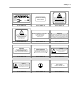
Safety 1-3 SERIAL # : XXXXX DATE : XXXXX Scottsdale, Arizona Model No: Manufactured: Serial No: Made in USA # 221-0004-0 WARNING NEVER OPERATE THE LASER SYSTEM WITHOUT CONSTANT SUPERVISION EXPOSURE TO THE LASER BEAM MAY CAUSE IGNITION OF COMBUSTIBLE MATERIALS WHICH CAN CAUSE SEVERE DAMAGE TO THE EQUIPMENT # 221-0007-0 # 221-0012-0 ! WARNING THIS LASER SYSTEM CONTAINS A CO 2 LASER IN A CLASS I ENCLOSURE. THE LASER SYSTEM HAS BEEN CLASSIFIED AS CLASS 3a DUE TO THE PRESENCE OF A VISIBLE LASER DIODE.
1-4 Safety DANGER # 221-0031-0 CAUTION LASER RADIATION DO NOT STARE INTO BEAM OR VIEW DIRECTLY WITH OPTICAL INSTRUMENTS CLASS 3A LASER PRODUCT LASER RADIATION - AVOID DIRECT EYE EXPOSURE LASER DIODE WAVELENGTH: 630-680 nm MAX. OUTPUT: 5 mW LASER DIODE WAVELENGTH: 630-680 nm MAX.
Safety 1-5 221-0020-0 221-0016-0 221-0015-0 221-0004-0 221-0023-0 221-0056-0 221-0021-0 221-0031-0 221-0007-0 221-0044-0 221-0045-0 221-0046-0 221-0047-0 221-0048-0 221-0049-0 221-0050-0 221-0051-0 221-0018-0 221-0017-0
1-6 Safety EU Compliance (CE) L A S E R S Y S T E M S I N C. Product Identification: X-600 and X2-600 Laser Engraving and Cutting Systems Manufacturer: Universal Laser Systems, Inc. st 16008 N. 81 St. Scottsdale, AZ 85260 Phone: (480) 483-1214 Fax: (480) 483-5620 USA This equipment Is manufactured in conformity with the following directives: 89/336/EEC 73/23/EEC 89/392/EEC (EMC Directive) (Low Voltage Directive) (Machinery Directive) based on the standards listed.
Safety 1-7 FCC Compliance This ULS laser system has been tested and found to comply with Federal Communication Commission (FCC) directives regarding Electromagnetic Compatibility (EMC). In accordance with these directives ULS is required to provide the following information to its customers. FCC Compliance Statement and Warnings This device complied with FCC Rules Part 15. Operation is subject to the following two conditions: 1. This device may not cause harmful interference, and 2.
SECTION 2 Installation Proper operating conditions are vital to a safe and productive environment. This section describes the ideal environment and setup of the laser system. Operating Environment Follow these guidelines to ensure a proper operating environment for the laser system. Operating the laser system outside of these guidelines can seriously damage the laser system and damages from this type of abuse WILL NOT be covered under warranty.
2-2 Installation • If planning to connect the laser engraving system to a computer through the parallel port, choose a location where the computer will be placed within 6 feet of the machine since this is the maximum recommended parallel cable length. Included with your system is a high quality, IEEE1284 compliant, 6-foot parallel printer cable. PLEASE USE THIS CABLE ONLY. DO NOT SUBSTITUTE IT WITH A LONGER OR LOWER QUALITY CABLE OTHERWISE FILE TRANSMISSION ERRORS MAY OCCUR.
Installation 2-3 If electrical power fluctuations, brown outs, or constant power outages are a problem in your area, an electrical line stabilizer, UPS (Uninterruptible Power Supply), or backup generator might be required. If installing any of these devices, make sure that they meet the electrical requirements of the laser system. If there is any type of electrical problem present, please contact a locally licensed electrical contractor to correct the problem.
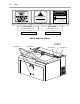
2-4 Installation DO NOT install forward incline, backward incline, in-line, or ventilator fans because these types of air handlers are inadequate and inappropriate for this type of installation. If your contractor has any questions concerning blower specifications or exhaust system requirements, please contact our Service Department directly before installation. The following diagram shows a typical exhaust system layout. Use this as a guideline to proper exhaust system installation.
Installation 2-5 FRONT VIEW FROM EXHAUST BLOWER Y-PIPE REDUCE TO 4 INCHES WITH A REDUCING COUPLER SHUT OFF GATE SHUT OFF GATE 4 INCH DIAMETER FLEXIBLE RUBBER HOSE Passing Through a Narrow Doorway If the doorway is not wide enough to allow to you roll the laser system through it, the system MUST be detached from the Cart Stand, rotated sideways, passed through the doorway, then re-attached to the Cart Stand.
2-6 Installation 3. Locate and disconnect the two white Power Supply Cable Connectors. Gently push the cables all the way down into the cavity of the Power Supply enclosure. Close and latch the Rear Cover by pushing down on the latch until it clicks. 4. Remove any packing materials or accessories from inside the Laser System. 5. Using strong shipping tape or rope, tape the front door closed so that it does not open up when you tilt it. 6.
Installation 2-7 Leveling the System 1. If the floor underneath the Laser System is uneven, the casters must be adjusted. Place a bubble level across the top of the legs directly above the front casters. Note the bubble position in its sight glass. Do the same for the back part of the legs and also note the position of the bubble in the sight glass. If the bubbles are in the same visual position, adjustment is not necessary and cart assembly is complete.
2-8 Installation Open the Rear Cover and visually locate the Laser Mounting Block(s), the Laser Latch(es), and Alignment Fork(s). Notice that the Alignment Fork(s) have two plates, one small and one large. Locate the gap between the two plates. Observe the “V” groove along the upper and lower part of the Laser Cartridge. Also locate the Alignment Plate at the end of the Laser Cartridge. Pick up the Laser Cartridge by the sides. Tilt the Laser Cartridge downward on a 30-degree angle.
Installation 2-9 Plug in the Power Connector(s). Note that the Power Connector that is physically located higher is the one that you connect to the TOP Laser Cartridge because it has an extra wire that powers the Red Diode Laser Pointer located in the Laser Cartridge. The power connector(s) are keyed so it will only insert one way. If you only have one laser, leave the BOTTOM power connector unplugged. Close the Rear Cover and push down on the latches until they “click”.
2-10 Installation Software Suggestions The following is a list of recommended software programs. We do not endorse any particular software program neither do we guarantee its full compatibility with the laser system. Please refer to the Appendices section on known bugs/anomalies related to these particular software programs, related versions, and ones that are not listed below.
Installation 2-11 Helpful Tip If you are having any problems printing a font and you cannot figure out what is going on, select the font and “convert to curves” or “convert to paths” in your graphics software. This will convert the font into a bitmapped image and will print correctly to the laser system. Refer to your graphics software on how to convert fonts. As you can see, we strongly recommend the use of True Type fonts only.
2-12 • • • • • Installation If the red dot is centered, installation is complete. Remove the masking tape. If you have second Laser Cartridge (the bottom one) installed, you must check it’s alignment also. To do this, you must first turn OFF the laser system. Disconnect the wire harness from the top Laser Cartridge and connect it into the bottom Laser Cartridge. Remember that only the TOP laser power connector has a wire that powers the Red Diode Pointer.
SECTION 3 System Operation In this section you will learn how the laser system actually works and will familiarize you with laser system terminology. We will then start working with the control panel and learn how to get around in the menu system. Since there are many features in this laser system, the menu system may seem complicated at first, but once you start using it, you will find out that it is a very simple system to operate.
3-2 System Operation NOTE: Before describing the complex functionality of the SUPERSPEED, in the following diagram, we demonstrate how a typical single-laser system works. We will then show how the SUPERSPEED builds upon this foundation and utilizes two Laser Cartridges to operate in a Dual Laser Single Beam Mode or Dual Laser Dual Beam Mode. Laser Cartridge The laser cartridge is a very sophisticated device.
System Operation 3-3 The “Focal Range” of the lens, where the beam is considered to be “in focus”, is equivalent to +/- 5% above and below the focus point. Shorter lenses produce a smaller spot size but also have a very narrow focal range. This means that it would only be useful for engraving very flat objects. The longer lenses have a much wider range of focus but also produce a larger spot size that would prohibit the engraving of fine detail.
3-4 System Operation The Liquid Crystal Display (LCD) The LCD is a four line display that displays the menus that control the laser system. It is a backlit type of display that enhances visibility even under low light environments. When the laser system is powered on, the laser system will perform a series of routines. “INITIALIZING” will display until the motion system and electronics have finished their routines.
System Operation 3-5 Green Indicator Light CONDITION ON OFF FLASHING REASON The laser system is powered up, the top door is closed and the system is ready to receive a file The laser system has finished processing a file and has returned to the home position The laser system has been paused while running a file The top or front door is open The laser system is firing the beam in the Alignment Mode The file is running Red Indicator Light CONDITION ON OFF FLASHING REASON The laser system is initializing
3-6 System Operation The “NEXT FILE” button displays the next file in the systems memory and makes it the current file and will stop at the last file in memory. The “PREV FILE” button displays the previous file in the systems memory and makes it the current file and will stop at the first file in memory. These buttons are inoperative if a file is currently running.
System Operation 3-7 The Menu System The LCD displays the menus of the laser system. Since this laser system has many features, we have included a “Menu System Flow Chart” on the next three pages. It diagrams and displays the menu items in the entire system and the button selections needed to access them. A description of each menu item follows the flow chart.
3-8 System Operation X X
System Operation 3-9 MODEL NAME VERSION XX-XX-XX-XX Menu Descriptions The remainder of this section will describe each one of the menus and their significance. READY Menu When the system is first powered on “INITIALIZING” will appear for approximately 30 seconds until the laser system finishes performing its routine. When the system has finished initializing, “READY” will appear in the display, indicating that the laser system is ready to accept files.
3-10 System Operation FILE DISPLAY Menu Appears automatically after the first file is downloaded completely into the laser systems memory. This is the menu that you will remain in most of the time when operating the laser system. It has been designed to show all pertinent operating information at a glance so that constantly jumping from menu to menu is not needed. The first line indicates the filename.
System Operation 3-11 There are two ways that a downloaded file will have a missing EOF. The first is if printing through the printer driver and printing is canceled, interrupted, or file size exceeds the remaining free memory space. If this occurs, chances are that the EOF never made it to the memory buffer and the memory buffer will show that it is empty or that the file does not exist. Part of the file might still remain in memory and might become mixed up with other files.
3-12 System Operation The Printer Driver compresses the file while it downloads to the laser system and the laser system decompresses the file while it runs. The amount of compression can be as little as 4 to 1 or as great as 48 to 1. This means that with 4 MB of RAM in the laser system, the buffer could hold the equivalent of 192MB worth of files provided they can be compressed 48 to 1. This gives the laser system the ability to store either larger or more files in memory.
System Operation 3-13 DOS POWER SETTINGS Menu The laser system allows eight different power settings to be saved, in non-volatile (permanent) memory, and used when processing a DOS based file. Since DOS based printer/plotter drivers do not have the ability to set the “POWER”, “SPEED”, and “PPI” settings, the settings must be set manually on the laser system. Think of it as being able to assign laser “POWER”, “SPEED”, and “PPI” to the pen numbers of a flatbed plotter.
3-14 System Operation OPTIONS Menu Selecting this menu will allow the access to turn on certain options that the laser system might have. ONE FILE MEMORY Menu Pressing “SELECT” key while cursor is on this line will toggle the setting on and off. When off, it enables the multiple file memory buffer system (default). When on, it disables the multiple file memory buffer and stores only one file at a time.
System Operation 3-15 AIR ASSIST Menu This class of laser system does have Air Assist as an option, but it is not computer controlled. Since we use the same menu system on other models, this menu selection for your model does absolutely nothing. If you did purchase the Air Assist option for this model, please refer to the instructions that came with that option. DUAL HEAD Menu This option is not available for this model of laser system.
3-16 System Operation To restore the focus position back to the original factory setting, go back into this menu and press the up and down arrow keys simultaneously. You will see the motion system move to the 1 inch horizontal and the 1 inch vertical position (factory default). Now select “YES, SAVE POSITION”. Press the “ESCAPE” button twice to exit back to the “MAIN” menu. Your settings will automatically be retained permanently in memory.
System Operation 3-17 If you would like to get the Rotary axis back to the original factory default setting, go back into the “SET ROTARY AXIS” menu. While in this menu, press the up arrow and down arrow keys simultaneously. The arm move will move back to its original factory default setting. Select “YES SAVE Y-AXIS”, and then press the “ESCAPE” key twice to exit back to the “MAIN” menu to store this setting permanently.
3-18 System Operation In order to use the “SERIAL” port, the communication settings MUST match those of the computer. Refer to the computer’s hardware and software manuals for details on setting up the computer’s serial port. If using the “SERIAL” port, select the fastest possible “BAUD” rate for communication since this effects how quickly the computer can send files to the laser system.
System Operation 3-19 DIAGNOSTICS Menu This menu leads to other menus that enable you to help diagnose problems, if they occur, with the laser system. It also will help our technicians solve problems that you may be experiencing. ALIGNMENT MODE Menu This menu allows access to firing the laser beam manually to determine if the laser systems optical alignment is correct. The factory setting is a very low power setting that is just strong enough to check the laser beam alignment.
3-20 System Operation MODEL NAME VERSION XX-XX-XX-XX ABOUT Menu Use the up and down arrow buttons to position the cursor on this menu item. Press the “SELECT” button and our copyright notice along with the current versions of firmware will be displayed. The firmware version numbers are a diagnostic aid to our service technicians. If you are having a problem with the laser system, a technician might ask you to read out the numbers in this display.
System Operation 3-21 Setting a new origin other than the default (0,0) position will shrink your field size. If you already have files already loaded into memory that utilize the entire engraving area, and you set a new origin, part of that graphic might fall out of the effective printing area. If you run this file, unexpected results can occur that might destroy your material in the engraving area.
3-22 System Operation The cursor in the display will be flashing on top of the tenths digit. You can now move the table up or down by pressing either the up or down arrow button. If you push the button once and let go quickly, the table will move in .1 inch increments. If you hold down the button, it will move fluidly. To make finer moves, press the “SELECT” button to bring the cursor over to the hundredths digit. Pressing the up or down arrow button once and letting go quickly will move the table in .
System Operation 3-23 If you find that you need to place your materials in a position other than the upper left hand corner, you can change the default focus position to anywhere in the field that you like. Please refer to that menu item selection earlier in this section. The Material Thickness (Z POSITION) Method The second method is to enter in the thickness of the material into the “Z POSITION” display. This method does not involve the use of the focus tool.
3-24 System Operation The AUTOFOCUS Method In order to use this method, you must first turn it ON. We described how to turn it ON earlier in this section. After you turn it ON, please follow the step by step instructions below. To Use AUTOFOCUS: • • The AUTOFOCUS sensor sends out an invisible beam across the table between the 1 inch and the 3 inch mark in the Y axis ruler for the M-300 Platform and the 2 and 4 inch mark for the V-400, X-600 and X2-600 Platform laser systems.
System Operation 3-25 To Adjust AUTOFOCUS: From time to time, you may need to re-adjust your AUTOFOCUS. The only time that you should need to re-adjust the AUTOFOCUS is when you have received a new or different length Focus Lens, have recently Flash upgraded the operating system of the laser, or had a dirty sensor or reflector and are adjusting it after you have cleaned those parts. • • • • • • Place a very flat object on the Engraving Table, within the AUTOFOCUS Zone, that is at least 1 inch thick.
SECTION 4 Running the System Step by Step In this section we will cover how to completely use the laser system to create a product from start to finish. From powering on everything to removing the finished product from the system, we will cover the entire process step by step. As an example, let’s engrave and cut out a key chain from a 2 by 4 inch, 1/8 inch thick piece of hardwood. Before continuing, please ensure that you have completely read and understood the entire manual up to this point.
4-2 Running the System Step by Step Focusing Before attempting to adjust the focal height, visually check to make sure that the table is down low enough to prevent the focus carriage from hitting into the piece of wood. With the top door still open, press the “Z” button on the control panel of the laser system. You will see the focus carriage move to the (1,1) position directly over the piece of wood.
Running the System Step by Step 4-3 It does not matter whether you bring the table up to go out of focus, or down, the effect is the same. You should experiment on some scrap material at another time and note the difference. In this example, we will engrave in precise focus. Once you have established focus, store your focus tool and close the top door. Creating the Graphic In your graphics program set your page size to the maximum size of the engraving area.
4-4 Running the System Step by Step Find the “PRINT” command within your graphics program and click on it. Depending on which graphics program you are using, the menu command “PRINT” may be in various locations within your program. Usually after clicking on “PRINT”, you will then need to click on “OK”. A status screen may now appear showing a percentage of completion. Once this status screen disappears, it does not mean that the file is totally in the laser systems memory.
Running the System Step by Step 4-5 We will also remind you again to please comply with the warning label below. Material Removing and Reloading Once the laser system has completed processing you material, the laser beam will turn off, the motion system will move to its home position in the upper right hand corner, the system will beep twice, and the green light on the control panel will glow continuously.
SECTION 5 Options & Accessories There are several options and accessories available for this laser system. The new 3D Effects option is now available as a standard feature. The Rotary Fixture, Cutting Table, Air Assist System, Air Assist Compressor, various Focus Lens Kits, and the Dual Head option are available at additional cost. 3D Effects The 3D Effects option can be used to create rubber stamps or produce a three-dimensional engraving appearance on other materials.
5-2 Options & Accessories 0 1 2 3 4 5 6 7 8 9 10 11 12 13 Plainville, KS 99924 100 Easy Street #117 Action Sports Equipment 1 2 3 PLACE STAMP IN AN UNUSED AREA 4 5 PREVIOUSLY COMPLETED STAMPS 6 7 GRAPHICS SOFTWARE PAGE LAYOUT 11 INCHES ( 292.1 mm) WIDE 8.5 INCHES ( 215.9 mm) TALL LANDSCAPE MODE 8 9 COMPUTER GRAPHICS SCREEN Place the stamp (on screen) where you want it to engrave in laser system. Avoid the spots where you have already engraved and cut out other stamps.
Options & Accessories 5-3 Settings for a 30 Watt System There is a considerable difference between rubber blends, thickness, and hardness between different manufacturers. Use these setting as a starting point for a 30 Watt system. You might need to experiment with different settings to obtain the desired results. As you can see, we set the page size in the driver equal to the graphics programs page size. We also selected "Add Shoulder” and “Normal Rubber Stamp”.
5-4 Options & Accessories Full Sheet Method The second method is to create a full sheet of rubber stamps and engrave them all at the same time. First create a stamp as a positive image as shown below. Create more stamps to fill the entire page. They can be the same stamp or different ones. If desired, output the page to a paper printer for proofreading. Printing out a positive image to a printer is easier to read and uses less toner or ink than a negative print.
Options & Accessories 5-5 In the laser systems printer driver, use the same settings as the previous example but with only minor modifications. In the “3D Effects” tab, select all three “Special” options; “Add Shoulder”, “Print as Negative Image” and “Print as Mirror Image” as the diagram below illustrates. Print to the laser system. Position the full sheet of rubber stamp material in the same upper left location on the engraving table and begin engraving.
5-6 Options & Accessories The Rotary Fixture is placed on the engraving table as the following diagram illustrates. Please refer to the instructions supplied with the Rotary Fixture on how to properly install and use this option. Cutting Table The purpose of the Cutting Table is to support the material that you are cutting off of the engraving table’s surface to minimize surface contact area. It also redirects exhaust airflow below and above the material for better smoke removal.
Options & Accessories 5-7 Air Assist System The Air Assist System consists of a nozzle that attaches to the focus carriage, Optics protection adapters, tubing, mounting brackets, needle valve, and pressure gauge. The purpose of this system is to force air or other types of gases directly onto the surface of your material to reduce the burning effects of the laser beam and helps disperse the smoke and gases created when cutting or engraving materials.
5-8 Options & Accessories Focus Lens Kits There are three optional Focus Lens Kits available other than the standard 2.0”, they are the 1.5”, 2.5”, and the 4.0” kits. Included in these kits are the focus lens, #3 mirror, front plate, thumbscrews, and a focus tool. Different lenses produce different spot sizes and have different focal ranges. For example, the 1.5” lens produces a spot size of .003” and has an effective focal range of +/- .075”.
Options & Accessories 5-9 Refer to the following chart for spot sizes and focal ranges of the lenses available. FOCAL LENGTH 1.5 “ 2.0 “ 2.5 “ 4.0 “ SPOT SIZE .003 “ .005 “ .007 “ .013 “ FOCAL RANGE + / - .075 “ + / - .100 “ + / - .125 “ + / - .200 “ If you would like to order any of the accessories described in this section, please speak with your salesperson or call us directly to place an order or to get current pricing. Most of these items are in stock and are available for immediate shipment.
SECTION 6 Sample Materials This section provides sample driver settings and helpful hints to get started engraving and/or cutting the materials listed. Safety NEVER LEAVE THE LASER SYSTEM RUNNING UNATTENDED FOR ANY REASON. Exposure to the laser beam can cause ignition of combustible materials. All laser cutting and engraving should be constantly supervised. NEVER OPERATE THE LASER SYSTEM WITHOUT A PROPERLY INSTALLED AND OPERATING EXHAUST SYSTEM.
6-2 Sample Materials NOTICE Laser engraving or cutting materials other than those described in this manual can be a safety hazard and can damage the laser system. The laser system operator is liable for any damages caused, in whole or in part, for any economic loss, physical injury, lost revenue, lost profits, lost savings or other indirect, incidental, special or consequential damages incurred. Damages to the laser system due to neglect, misuse, or operator error WILL NOT be covered under warranty.
Sample Materials 6-3 NOTE When engraving very small objects, top speed cannot be achieved because acceleration and deceleration of the motion system requires time and distance. The laser system will automatically adjust itself to a maximum engraving speed that it can achieve due to the size and position of the graphic. This is why you might notice that there might be no difference in engraving time on certain graphics whether you choose 100% speed or less.
6-4 Sample Materials ACRYLIC - CAST AND EXTRUDED RASTER ENGRAVING LASER WATTAGE 15 20 25 30 35 40 45 50 55 60 65 70 75 80 85 90 95 100 POWER 70 53 42 35 30 26 23 21 19 18 16 15 14 13 12 12 11 11 SPEED 55 55 55 55 55 55 55 55 55 55 55 55 55 55 55 55 55 55 PPI 500 500 500 500 500 500 500 500 500 500 500 500 500 500 500 500 500 500 PASS 1 1 1 1 1 1 1 1 1 1 1 1 1 1 1 1 1 1 DEPTH .001” .001” .001” .001” .001” .001” .001” .001” .001” .001” .001” .001” .001” .001” .001” .001” .001” .
Sample Materials 6-5 COMMENTS There are two types of acrylic available, cast and extruded. Cast turns white or frosted and extruded remains clear when engraved. Use extruded acrylic for paint filled engraving and cast for regular engraving. Cast engraves better without masking. Lightly engrave the surface to frost it with a low power setting such as the first setting listed above.
6-6 Sample Materials ACRYLIC - MIRRORED RASTER ENGRAVING LASER WATTAGE 15 20 25 30 35 40 45 50 55 60 65 70 75 80 85 90 95 100 POWER 80 60 48 40 34 30 27 24 22 20 18 17 16 15 14 13 13 12 SPEED 55 55 55 55 55 55 55 55 55 55 55 55 55 55 55 55 55 55 PPI 500 500 500 500 500 500 500 500 500 500 500 500 500 500 500 500 500 500 PASS 1 1 1 1 1 1 1 1 1 1 1 1 1 1 1 1 1 1 DEPTH .003” .003” .003” .003” .003” .003” .003” .003” .003” .003” .003” .003” .003” .003” .003” .003” .003” .
Sample Materials 6-7 COMMENTS Engraving mirrored acrylic is similar to engraving regular acrylic. The idea is to engrave through the mirrored backing enough to begin to penetrate into the acrylic. Engraving deeply will cause a crusty residue to form just like with non-mirrored acrylic. A double image will appear if engraving on the front side of the mirror. It is not necessary to mask the backside when engraving because the mirrored backing shields the acrylic from smoke damage.
6-8 Sample Materials ANODIZED ALUMINUM RASTER ENGRAVING LASER WATTAGE 15 20 25 30 35 40 45 50 55 60 65 70 75 80 85 90 95 100 POWER 90 68 54 45 39 34 30 27 25 23 21 19 18 17 16 15 14 14 SPEED 55 55 55 55 55 55 55 55 55 55 55 55 55 55 55 55 55 55 PPI 500 500 500 500 500 500 500 500 500 500 500 500 500 500 500 500 500 500 PASS 1 1 1 1 1 1 1 1 1 1 1 1 1 1 1 1 1 1 DEPTH .001” .001” .001” .001” .001” .001” .001” .001” .001” .001” .001” .001” .001” .001” .001” .001” .001” .
Sample Materials 6-9 COMMENTS There is a process called Laser Color Marking which enables the color filling of anodized aluminum. First, coat or spray the aluminum with a clear acrylic finish. After the finish has thoroughly dried, laser engrave the graphic onto the aluminum. Then take a water based marker, such as those found in an art supply store, and swab on the ink into the engraved area. You can actually see the ink get absorbed into the engraved area but not the unengraved area.
6-10 Sample Materials BRASS - PAINTED RASTER ENGRAVING LASER WATTAGE 15 20 25 30 35 40 45 50 55 60 65 70 75 80 85 90 95 100 POWER 90 68 54 45 39 34 30 27 25 23 21 19 18 17 16 15 14 14 SPEED 55 55 55 55 55 55 55 55 55 55 55 55 55 55 55 55 55 55 PPI 500 500 500 500 500 500 500 500 500 500 500 500 500 500 500 500 500 500 PASS 1 1 1 1 1 1 1 1 1 1 1 1 1 1 1 1 1 1 DEPTH .001” .001” .001” .001” .001” .001” .001” .001” .001” .001” .001” .001” .001” .001” .001” .001” .001” .
Sample Materials 6-11 COMMENTS The manufacturing processes for coated brass varies from one vendor to another. Some manufacturers do not polish the brass before coating it. Since CO2 lasers at this power level do not engrave into metals when the coating is removed, the tarnished brass underneath will have a dull appearance that will need to be polished with a brass polishing compound.
6-12 Sample Materials CORIAN / AVONITE / FOUNTAINHEAD RASTER ENGRAVING LASER WATTAGE 15 20 25 30 35 40 45 50 55 60 65 70 75 80 85 90 95 100 POWER 100 100 100 100 100 100 100 100 100 100 100 100 100 100 100 100 100 100 SPEED 7 9 12 14 16 19 21 23 26 28 30 33 35 37 40 42 44 47 PPI 500 500 500 500 500 500 500 500 500 500 500 500 500 500 500 500 500 500 PASS 1 1 1 1 1 1 1 1 1 1 1 1 1 1 1 1 1 1 DEPTH .015” .015” .015” .015” .015” .015” .015” .015” .015” .015” .015” .015” .015” .015” .015” .015” .015” .
Sample Materials 6-13 COMMENTS If paint filling, mask the material first, then engrave through the masking. In this way, when ready to paint fill, the material is already masked. Spray painting seems to be the easiest. Use the paint sparingly. Excess paint can accumulate on the edges of the engraving, which will make mask removal difficult and leave unsightly ridges. It is best to apply several lighter coats than one heavy coat of paint. Remove the masking after the paint has dried.
6-14 Sample Materials CORK RASTER ENGRAVING LASER WATTAGE 15 20 25 30 35 40 45 50 55 60 65 70 75 80 85 90 95 100 POWER 100 100 100 100 100 100 100 100 100 100 92 86 80 75 71 67 63 60 SPEED 20 27 33 40 47 53 60 67 73 80 80 80 80 80 80 80 80 80 PPI 500 500 500 500 500 500 500 500 500 500 500 500 500 500 500 500 500 500 PASS 1 1 1 1 1 1 1 1 1 1 1 1 1 1 1 1 1 1 DEPTH .010” .010” .010” .010” .010” .010” .010” .010” .010” .010” .010” .010” .010” .010” .010” .010” .010” .
Sample Materials 6-15 COMMENTS Cork is not very popular for engraving but it does engrave and cut nicely. Cork is mainly used for making gaskets by vector cutting the gasket patterns. LASER CUTTING THIS MATERIAL CAN CAUSE FLAMING AND SPARKING. Use caution when attempting to cut this material. It would be better to use a longer focal length lens to prevent the lens from being damaged during processing. NEVER leave the machine unattended while processing any material.
6-16 Sample Materials DELRIN (SEAL PRESS) RASTER ENGRAVING LASER WATTAGE 15 20 25 30 35 40 45 50 55 60 65 70 75 80 85 90 95 100 POWER 100 100 100 100 100 100 100 100 100 100 100 93 87 81 77 72 69 65 SPEED 13 17 21 25 29 33 38 42 46 50 55 55 55 55 55 55 55 55 PPI 500 500 500 500 500 500 500 500 500 500 500 500 500 500 500 500 500 500 PASS 1 1 1 1 1 1 1 1 1 1 1 1 1 1 1 1 1 1 DEPTH .015” .015” .015” .015” .015” .015” .015” .015” .015” .015” .015” .015” .015” .015” .015” .015” .015” .
Sample Materials 6-17 COMMENTS The laser system can be used to make dies for seal presses. It can engrave and cut out a typical Notary Seal in less than 5 minutes. Create the male with a white graphic and a black background. Mirror the image and invert it by making the background white and the graphic black. Add a .010 inch black outline to the graphic portion of the female side.
6-18 Sample Materials GLASS / CRYSTAL RASTER ENGRAVING LASER WATTAGE 15 20 25 30 35 40 45 50 55 60 65 70 75 80 85 90 95 100 Note: Engrave at 333 DPI POWER 100 100 100 100 100 100 100 100 100 100 100 100 100 100 100 100 100 100 SPEED 7 9 12 14 16 19 21 23 26 28 30 33 35 37 40 42 44 47 PPI 300 300 300 300 300 300 300 300 300 300 300 300 300 300 300 300 300 300 PASS 1 1 1 1 1 1 1 1 1 1 1 1 1 1 1 1 1 1 DEPTH .001” .001” .001” .001” .001” .001” .001” .001” .001” .001” .001” .001” .001” .001” .001” .001” .
Sample Materials 6-19 COMMENTS Glass engraving is different from other types of engraving. A CO2 laser cannot engrave into the glass nor can it cut glass. Instead, laser interaction with glass causes the surface of the glass to appear frosted. Sometimes, placing a piece of newspaper on the glass and dampening is with water will improve the appearance of the engraving. Another method is to apply transfer tape to the glass, wet it with water from a spray bottle, and laser engrave it.
6-20 Sample Materials LEATHER RASTER ENGRAVING LASER WATTAGE 15 20 25 30 35 40 45 50 55 60 65 70 75 80 85 90 95 100 POWER 56 42 34 28 24 21 19 17 15 14 13 12 11 11 10 9 9 8 SPEED 55 55 55 55 55 55 55 55 55 55 55 55 55 55 55 55 55 55 PPI 500 500 500 500 500 500 500 500 500 500 500 500 500 500 500 500 500 500 PASS 1 1 1 1 1 1 1 1 1 1 1 1 1 1 1 1 1 1 DEPTH .001” .001” .001” .001” .001” .001” .001” .001” .001” .001” .001” .001” .001” .001” .001” .001” .001” .
Sample Materials 6-21 COMMENTS Leather is a very simple material to engrave and most types of leather engrave very well with the laser system. Simulated leather engraves well also, but the results are not as nice as with the real thing. Engraving lightly will turn the surface of the leather dark brown giving it a high contrast in appearance. Try engraving at a light power setting first. If the result is not deep enough the job can be run again over the same spot.
6-22 Sample Materials MARBLE RASTER ENGRAVING LASER WATTAGE 15 20 25 30 35 40 45 50 55 60 65 70 75 80 85 90 95 100 POWER 100 100 100 100 100 100 100 90 82 75 69 64 60 56 53 50 47 45 SPEED 19 25 32 38 44 51 55 55 55 55 55 55 55 55 55 55 55 55 PPI 500 500 500 500 500 500 500 500 500 500 500 500 500 500 500 500 500 500 PASS 1 1 1 1 1 1 1 1 1 1 1 1 1 1 1 1 1 1 DEPTH .003” .003” .003” .003” .003” .003” .003” .003” .003” .003” .003” .003” .003” .003” .003” .003” .003” .
Sample Materials 6-23 COMMENTS Most marble and polished stones will turn white when engraved. Masking is not necessary and light engraving works out better than heavy and deep engraving. Engraving deeply will cause a highly detailed image to appear washed out. The objective is to engrave deep enough to turn the marble white and provide a good contrast. Too much power can also cause the material to discolor and turn brown as if it were burned.
6-24 Sample Materials MAT BOARD RASTER ENGRAVING LASER WATTAGE 15 20 25 30 35 40 45 50 55 60 65 70 75 80 85 90 95 100 POWER 90 68 54 45 39 34 30 27 25 23 21 19 18 17 16 15 14 14 SPEED 55 55 55 55 55 55 55 55 55 55 55 55 55 55 55 55 55 55 PPI 250 250 250 250 250 250 250 250 250 250 250 250 250 250 250 250 250 250 PASS 1 1 1 1 1 1 1 1 1 1 1 1 1 1 1 1 1 1 DEPTH .005” .005” .005” .005” .005” .005” .005” .005” .005” .005” .005” .005” .005” .005” .005” .005” .005” .
Sample Materials 6-25 COMMENTS Mat board (thick cardboard) is an excellent material to use for architectural modeling and for picture framing. It cuts and engraves very neatly and cleanly. It comes in a variety of shades and colors. Patterns can be engraved on the surface with a power setting for light engraving which just breaks through the very thin top layer and exposes the lighter colored underlying substrate.
6-26 Sample Materials MELAMINE - STANDARD ENGRAVING RASTER ENGRAVING LASER WATTAGE 15 20 25 30 35 40 45 50 55 60 65 70 75 80 85 90 95 100 POWER 100 100 100 100 100 100 100 100 100 100 100 100 100 100 100 95 90 85 SPEED 10 13 17 20 23 27 30 33 37 40 43 47 50 53 55 55 55 55 PPI 500 500 500 500 500 500 500 500 500 500 500 500 500 500 500 500 500 500 PASS 1 1 1 1 1 1 1 1 1 1 1 1 1 1 1 1 1 1 DEPTH .020” .020” .020” .020” .020” .020” .020” .020” .020” .020” .020” .020” .020” .020” .020” .020” .020” .
Sample Materials 6-27 COMMENTS Engraving melamine is very similar to engraving regular wood with the added benefit of a consistent surface finish and uniform base material composition. Unlike regular wood that has grain patterns and density variations, melamine, when laser engraved, produces a flat and even engraved area. This characteristic gives this material superior engraving and paint filling qualities.
6-28 Sample Materials MELAMINE - PHOTO/CLIPART ENGRAVING RASTER ENGRAVING LASER WATTAGE POWER SPEED 15 100 28 20 100 37 25 100 46 30 100 55 35 90 55 40 79 55 45 70 55 50 63 55 55 57 55 60 53 55 65 48 55 70 45 55 75 42 55 80 39 55 85 37 55 90 35 55 95 33 55 100 32 55 COMMENTS: Engrave unmasked. Use a resolution of 500 DPI. PPI 500 500 500 500 500 500 500 500 500 500 500 500 500 500 500 500 500 500 PASS 1 1 1 1 1 1 1 1 1 1 1 1 1 1 1 1 1 1 DEPTH .008” .008” .008” .008” .008” .008” .008” .008” .008” .
Sample Materials 6-29 COMMENTS Engraving photographs can be challenging at first but becomes easier once there is an understanding of what to look for and how to achieve the desired results. In an image processing software, scan the image in at 300 DPI. Adjust the brightness and the contrasts to brighten the light colors and darken the dark colors. The photo might look better by using a sharpening filter to sharpen up the image slightly. The next step is to select a halftone pattern.
6-30 Sample Materials PLASTIC - ENGRAVERS MICROSURFACED RASTER ENGRAVING LASER WATTAGE 15 20 25 30 35 40 45 50 55 60 65 70 75 80 85 90 95 100 POWER 70 53 42 35 30 26 23 21 19 18 16 15 14 13 12 12 11 11 SPEED 55 55 55 55 55 55 55 55 55 55 55 55 55 55 55 55 55 55 PPI 500 500 500 500 500 500 500 500 500 500 500 500 500 500 500 500 500 500 PASS 1 1 1 1 1 1 1 1 1 1 1 1 1 1 1 1 1 1 DEPTH .003” .003” .003” .003” .003” .003” .003” .003” .003” .003” .003” .003” .003” .003” .003” .003” .003” .
Sample Materials 6-31 COMMENTS Laser engraveable plastic comes in many different colors, thickness, coatings, and surface textures. Most engravers plastic will engrave and cut well with the laser system as long as it is microsurfaced and formulated for laser engraving. Removal of large amounts of material will warp the plastic. You might need to tape it down or hold it down flat somehow to prevent it from curling as you engrave.
6-32 Sample Materials RUBBER STAMPS RASTER ENGRAVING LASER WATTAGE 15 (Not recommended) 20 (Not recommended) 25 30 35 40 45 50 55 60 65 70 75 80 85 90 95 100 POWER N/A N/A 100 100 100 100 100 100 100 100 100 100 100 100 100 100 100 100 SPEED N/A N/A 13 16 19 21 24 27 29 32 35 37 40 43 45 48 51 53 PPI N/A N/A 500 500 500 500 500 500 500 500 500 500 500 500 500 500 500 500 PASS N/A N/A 1 1 1 1 1 1 1 1 1 1 1 1 1 1 1 1 DEPTH N/A N/A .030” .030” .030” .030” .030” .030” .030” .030” .030” .030” .030” .
Sample Materials 6-33 COMMENTS To create a rubber stamp, use the “3D Effects” tab in the driver (Section 3). In the above example, only one pass is necessary to achieve a deeply engraved rubber stamp. When cutting out the rubber stamp, we recommend using a very low PPI setting. This setting spreads the laser pulses far enough apart that they just touch at the edges.
6-34 Sample Materials SIGN VINYL RASTER ENGRAVING LASER WATTAGE 15 20 25 30 35 40 45 50 55 60 65 70 75 80 85 90 95 100 POWER 100 100 100 100 100 100 100 100 100 100 100 100 100 100 100 94 89 85 SPEED 10 13 17 20 23 27 30 33 37 40 43 47 50 53 55 55 55 55 PPI 500 500 500 500 500 500 500 500 500 500 500 500 500 500 500 500 500 500 PASS 1 1 1 1 1 1 1 1 1 1 1 1 1 1 1 1 1 1 DEPTH .015” .015” .015” .015” .015” .015” .015” .015” .015” .015” .015” .015” .015” .015” .015” .015” .015” .
Sample Materials 6-35 COMMENTS Sign vinyl comes in a wide variety of colors, patterns, thickness, finishes, and reflectivity. There are a few methods for using sign vinyl with the laser system. One method is to vector cut (unmasked) through the vinyl but not through the backing. This technique provides results equivalent to a vinyl cutter machine. Once the vinyl has been cut, remove the excess vinyl, apply transfer tape and use a squeegee to remove trapped air bubbles.
6-36 Sample Materials WOOD RASTER ENGRAVING LASER WATTAGE 15 20 25 30 35 40 45 50 55 60 65 70 75 80 85 90 95 100 POWER 100 100 100 100 100 100 100 100 100 100 92 86 80 75 71 67 63 60 SPEED 14 19 23 28 33 37 42 47 51 55 55 55 55 55 55 55 55 55 PPI 500 500 500 500 500 500 500 500 500 500 500 500 500 500 500 500 500 500 PASS 1 1 1 1 1 1 1 1 1 1 1 1 1 1 1 1 1 1 DEPTH .020” .020” .020” .020” .020” .020” .020” .020” .020” .020” .020” .020” .020” .020” .020” .020” .020” .
Sample Materials 6-37 COMMENTS When engraving wood with a laser, a brown, maple syrup like residue will deposit on the surface of the wood. This is normal and impossible to eliminate by POWER, SPEED, or PPI changes. More residue will be present when engraving deeper and/or slower. This residue washes off with water and a sponge. We recommend using a kitchen sponge with a nylon string mesh wrapped around it. Dampen the sponge and wipe off the residue. A damp chamois cloth works well also.
6-38 Sample Materials with the laser system, add glue to the veneer, and apply the veneer into the engraved area of the other piece of wood and let dry. After the glue has thoroughly dried, sand the veneer until it is flush with the base wood. A good veneer to use is one with an adhesive backing. Once cut, place the veneer into its proper place on the engraved wood block and with a clothes iron, and iron the veneer into the engraved wood.
SECTION 7 Maintenance Keeping the laser system clean will ensure the highest quality engraving. The frequency of cleaning will depend entirely on the type of material being engraved, the performance of your exhaust blower, the operating environment, and the amount of laser system usage over a given period of time. Dirt or debris that is allowed to build up on the motion system components will cause uneven or rough engraving, or loss of engraving position as well as premature component failure.
7-2 Maintenance
Maintenance 7-3 System Cleaning • Turn off and unplug the laser system. • Open the Top Door and thoroughly remove all loose dirt and debris from inside the machine with a vacuum cleaner. • Clean the Engraving Table surface with either a soap solution, alcohol, or acetone, and paper towels. NEVER pour or spray any solution directly into the laser system.
7-4 Maintenance #2 Mirror To gain access to the #2 Mirror, the mirror cover must be removed. Remove the thumbscrew, slide the cover to the right slightly and lift straight up. Inspect the #2 Mirror and clean it only if there is debris present. There are two ways to clean the mirror, with a moistened cotton swab or a moistened lens tissue. To clean the #2 Mirror with a cotton swab, moisten the cotton swab with the Lens Cleaning solution supplied with the laser system.
Maintenance 7-5 #3 Mirror and Focus Lens You must remove the front cover to the Focus Carriage to gain access to the #3 Mirror and the Focus Lens. To do this, hold the front cover with one hand and with the other hand, remove the three(3) thumbscrews that attach the front cover to the Focus Carriage, and pull the front cover straight out. You will notice that the #3 Mirror and the Focus lens are both mounted to the front cover. Refer to the diagram below.
7-6 Maintenance Beam Window The Beam Window is where the laser beam enters into the engraving area. It is located in the upper left hand corner of the engraving area against the back wall and is yellow in color. It is not necessary to remove the Beam Window for cleaning since it can only get dirty on the front side. The backside is in a sealed environment. To clean the Beam Window, moisten a cotton swab and gently roll it across. Basically, clean it in the same manner as the #2 Mirror.
Maintenance 7-7 Adjustments and Lubrication There are no periodic adjustments required. The bearings in the motion system will self adjust to take up any clearances as they begin to wear. The belts are fiber reinforced and will not stretch under normal use so that periodic tension adjustment is not necessary. Optical alignment is not necessary because the laser cartridge and the #2 Mirror are fixed. All bearings in the system are sealed and do not require lubrication.
7-8 Maintenance Cooling Fan Filters This air-cooled laser system will require periodic cleaning of the cooling fan filters. Since ambient air is used to cool the laser tube, the air must be filtered before it enters the inside of the laser system otherwise dirt and dust can build up inside of the laser system and damage it. The contaminants reduce the laser system’s cooling ability and will cause the laser tube to overheat.
SECTION 8 Troubleshooting Engraving Quality Problem “Fuzzy” looking raster engraving or small text appears like a “double image” Fine detail is missing such as the serif’s of characters or thin lines of script fonts when raster engraving Vertical or diagonal background pattern present when raster engraving large areas and/or large amounts of material • • Possible Cause Dirty laser system Graphic, graphic software, graphic software setup, color palette, monitor display colors, or driver settings have ch
8-2 Troubleshooting Raster engraving appears sharp on both ends of the engraving but fuzzy in the middle • • • Dirty laser system Something is loose System needs tuning • Worn X-axis belt and/or drive gear • • • • Engraving does not appear as deep as it normally does • • • Tickle setting too low Faulty laser tube Graphic, graphic software, graphic software setup, color palette, monitor display colors, or driver settings have changed • • • • • • Out of focus Material or material density has chan
Troubleshooting Engraving appears “halftoned” and not solidly filled when using colors other than black • Graphic, graphic software, graphic software setup, color palette, monitor display colors, or driver settings have changed • Wavy lines when vector engraving or cutting • Running too fast • • • Dirty laser system Worn or faulty bearings • • • Arm is out of square • • • Firmware needs to be updated Angled cuts are a normal condition if they are equal on all sides of the object.
8-4 Troubleshooting Operational Focus carriage looses X-axis position and slams into the left or right side of the rail during high speed raster engraving When homing, the arm slams repeatedly for a few seconds When focusing, the Z-axis table only moves in one direction • Mechanical interference • • • Dirty laser system CPU overheating • • • Focus carriage X-axis bearing tensioning arm too tight or binding • If the pattern is excessive: • X-belt too tight • Worn or binding X-axis bearings • Wo
APPENDIX
Appendix A - Limited Warranty Please refer to the Warranty Registration Form included with your shipment.
Appendix B - Specifications Model Number X-600 or X2-600 Resolution 1000 x 1000 DPI, 500 x 500 DPI, 333 x 333 DPI, 250 x 250 DPI 200 x 200 DPI, Draft Computer Interface Windows 95, 98, and HPGL Table Size 37” x 23” (939.8 mm x 584.2 mm) Work Area 32” x 18” (812.8 mm x 457.2 mm) Maximum Part Size 37” (939.8 mm) wide x 23” (584.2 mm) deep x 9” (228.
Appendix C - Using DOS Based Programs DOS software is not standardized and each application will work differently. When using DOS applications, it is not possible to print through the Windows Printer Driver and for this situation, the system has been designed to automatically emulate a Hewlett Packard plotter. Plotters use a special language called HPGL that the laser system has been designed to accept. When configuring the DOS based program, select the HP7475 plotter (or larger) as the printing device.
Appendix D - Using Macintosh Computers The laser system has primarily been designed to run under the Windows 95 or Windows 98 operating system. There is no Macintosh Driver available for this Platform at this time, however, there may be one in the future. Once in awhile you might want to log on to our web-site www.ulsinc.com to see if there are developments in this area.
Appendix E - Serial Port Cable Requirements
Appendix F - How To Get Help Step 1: Determine exactly what the problem is. Refer to “Section 8 – Troubleshooting” for a possible solution. Step 2: Try to recreate the problem and write down the circumstances in which the problem occurred. Be prepared to describe all pertinent information about the computer being used with the laser cutting and engraving system such as software, operating system and computer type. Have the serial number of the laser system available.