P u t t in g You in Con t r ol of Tod ay 's Tech n ology ViewSonic Tweety RF Remote Product Specification Work Order: 50-954 November 05, 2001 Rev. 2.9A URCs: 4012B00 Author: Jason Etter Viewsonic Tweety RF Remote Universal Electronics Inc. Confidential Rev 2.
Revision History Product Revision History Specification Rev Date A B 12/6/00 12/20/00 C 01/12/01 D 02/05/01 E 02/13/01 Software Ver Date Sect. 1.1 3.2.4 3.3.2 3.3.3 4 5 6.1.2 6 6.1.6 7.4 1.0 6.2 ALL 3.3.2, 3.2.4, 3.2.5 1.1 3.1.1 3.1.2 3.1.3 3.2.4 3.3.1 3.3.2 3.3.3 3.3.5 6 7.4 8.6 Rev1.0 Rev 1.1 1.1 3.2.1/2 3.2.4 3.3 3.3.1 3.3.3 3.3.5 3.3.9 4 6 7.4 10.1 Viewsonic Tweety RF Remote Universal Electronics Inc.
Rev 2.0 3.1.1 3.3 3.1.3 3.1.4 3.1.5 3.4 1.1, 4, 6.1.1 4 4.1 Rev 2.1 2.2 5.1.1 5.1.2 5.1.3 2.1.1 3.1.5 3.1.6 10.2 2.3 2.4 2.5 2.6 3.4 & 3.4.7.1 3.4.6.1 5.1.2 5.1.2 7.6 11 3.2.4, 3.4.6.2 3.4 3.4.3 3.4.5 4.12 2.7 3.2.4, 3.4.6.2, 7.6 11 2.8 2.9 11 3.2.4, 3.4.6.2 3.4 2.91 1.1 4.9 Viewsonic Tweety RF Remote Universal Electronics Inc.
Approvals: Jerry Bardin VP, Engineering (UEI) Date: Jakob Kishon Viewsonic Steve Gates Sr.
Table of Contents Product Revision History ...........................................................................................................................................................................3 1 Purpose and Scope .....................................................................................................................................................................8 1.1 1.2 2 Description......................................................................................
5.1.8 6 Communication Link...........................................................................................................44 Electrical Requirements .................................................................................................................................................................46 6.1 Power.............................................................................................................................................46 6.2 Visible LEDs ...............
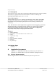
Purpose and Scope 1.1 Description The Viewsonic-Tweety remote will be a dedicated 2.4 gHz RF remote with 10 channel capability. This will be a 6V product and will use 4 AAA batteries. It will use a Samsung 16K (S3P/C80F9XFE-QZR5) (QFP) Micro-controller. Network Description: The RF modules support up to 10 channels in the ISM band of 2446.7MHz to 2464.3MHz, providing a form of frequency division multiple access (FDMA).
2.1.1 Customer Specification NMB RF-Receiver and Host Image Processor rev 0.9 (This spec takes precedence a changes to the receiver software must also be made to the remote and keyboard) 2.1.2 Other Product Documentation N/A 2.2 UEI Standard Documentation UEI SPEC 0020, UEI SPEC HE003, UEI SPEC 0002 2.2.1 UEI Standard Glossary N/A 2.2.2 UEI Standard Hardware General Information Refer to Section 3.1.3 2.2.3 UEI Standard Operational Features Descriptions 2.2.
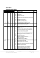
Channel Lock Device Mode Keys No DEDICATED Dual Functional via Shift Key a) One Time Use b) Shift Lock w/Time-Out E2 Auto-Sizing E2 Device Mode Lock E2 Upgradeable via Modem (997) E2 Upgradeable via 6 pin interface Factory Test Mode Favorite Channel Scan (996) Functional Keys – Additional a) brightness Control b) Color Control c) Menu d) Shifted Functions With/without time-outs e) Teletext – Simple f) Teletext – Fastext Functional Keys – Standard Hidden Keys High Frequency Capable ID Code Verification ID
Punch Through to Last Device (by Key Group) Record Safety Remote Finder with Lock Option No No No Reset to Defaults a) Operational Reset (980) b) Manufacturing Reset (981) Section 3.3.4 Set Up Section 3.3.2 Simultaneous Double Key Press - Standard Action Simultaneous Double Key Press - Alternative Action Sleep Feature via UEI w/Lock Option Step and Set (991) Stuck key Time-Out No Custom Custom No No No No Custom Keypress = 60 sec. Pointer = 120 sec.
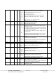
3.1.4 Mechanical Information 1. 2. 3. 4. 5. 6. 7. Battery Compartment Colors & Labels Force versus Travel (Keypad with Polydome) IR Lens Key Clearance Keypad Definition List of Consigned Parts 8. 9. 10. 11. 12. 13. 14. 15. 16. 17. Material Overlay Packaging Requirements in BOM Plastic Case design or rendering included Prototype/Model Sliding Door Unique Parts URC with B00# Weight Other (describe) Yes Section 8.2.4 Section 8.3.
3.1.6 Miscellaneous Information 1. Batteries (Included) 2. Battery Cover a) Rating label silk screened on outside of battery door 3. 4. 5. 6. 7. 8. 9. 10. 11.
3.2.
3.3 Operational Features Conventions and Notations The operation of the remote control and the programming sequence use the following shorthand notations. The relational operator <<>> around a key is an instruction to press and hold the key for 3 seconds. For example: <> Press RESYNC and hold for 3 seconds The relational operator <> around a key is an instruction to press the key and then release. For example: Viewsonic Tweety RF Remote Universal Electronics Inc.
3.4 Remote UEI Key and Pointing Device Data Packet Data Packet Definition: Byte10 (MSB) Byte09 Byte08 Byte07 Byte06 Byte05 0x0F 0x0F 0x0F 0x0F 0x55 0x55 Sync Bytes Preamble 32 bits 16 bits Sync Bytes: signal input.
CheckSum: The sum of Device Number + Device Address / Status + X-Coordinate + Y-Coordinate/Scan Code. (Add all the indicated bytes without carry’s). LEFT/RIGHT MOUSE key Operation 1. When the key is pressed, its corresponding pointing device left key status (Bit 3) in the Device Address / Status Byte will be set. This bit will be set as long as the key is held down, and it will be reset (or cleared) when the key is released. 1.1.
a) If the Pointing Device is not active, no data packet will be transmitted. Both keys must be released for the remote to return to its normal operation b) If the Pointing Device is active prior to the key presses as described in 2.2 above, the transmitted data packet will have Right key status bit in the Device Address / Status Byte reset and the X-Coordinate Byte and Y-Coordinate / Scan Code Byte contained the X and Y positional values of the Pointer movement. 3.
Re-Sync Data Packet Byte10 (MSB) Byte09 Byte08 Byte07 Byte06 Byte05 0x0F 0x0F 0x0F 0x0F 0x55 0x55 Sync Bytes Preamble 32 bits 16 bits Byte04 0-0x63 (0-99 decimal) Device Number 8 bits Byte03 Dev Addr / Status 8 bits Byte02 Byte01 Byte0 (LSB) 0x00 0x76 0xYY X Coord 8 bits Y Coord / ScanCode 8 bits CheckSum 8 bits How does the Re-Sync operates and When the “Re-Sync” code is sent: Activating the key allows the user to send the “signature data” and to synchronize the RF Tra
3.4.1 Definitions Stuck Key Time-out After any key is pressed continuously for 60 seconds, the remote will stop sending data packets and turn off RF transmission to conserve battery life. Transmission can begin again, after all keys are released and key is pressed.
Sleep Data Packet Byte10 (MSB) Byte09 Byte08 Byte07 Byte06 Byte05 0x0F 0x0F 0x0F 0x0F 0x55 0x55 Sync Bytes Preamble 32 bits 16 bits Byte04 0-0x63 (0-99 decimal) Device Number 8 bits Byte03 Dev Addr / Status 8 bits Byte02 Byte01 Byte0 (LSB) 0x00 0xFD 0xYY X Coord 8 bits Y Coord / ScanCode 8 bits CheckSum 8 bits How and When the Sleep code is sent: The Sleep Code Data Packet will be sent: After depressed key, say, is released and two Data-Packets of K1 Break Code sent, the RF
If another key, say, is pressed while is still held down, the Make code data packet of the same K1 key will be sent out as defined above. Until is released, two data packets of Break code will be sent with 10 ms delay between data packet. Since is now still held down, two data packets of Make code will be sent with 10 ms delay between data packets. Note: Packet gap between the last Break Code of K1 sent and the first Make Code of K2 sent is 10 ms..
Timing Events versus Data Packet transmission for various operational situations: 3.4.
Time Event / Data Packet Transmission Diagram (continued) Te_2 --------------------------- // ------------------------ // ------------------ 60 seconds ---------------- // ------------------------ // ----------------- ~ 70ms -- // ~10ms~ Te_2a Te_3 Te_3a, Te_1a Te_1 ~10ms~ Make Make Break Break Te_3b, Te_6a Te_3c, Te_6a Te_1a Make Te_4 Make - // ---- 70ms --- // ----- Te_4a Notes: Make StkKy Sleep Te_4b Te_5 Te_5a Te_6a - // ---- 70ms -- // ---- Time values are approximate and NOT to sca
Key Type Data Packet Transmission, a Summary: All keys including the pointing device buttons are Make/Break type. When a key or button is pressed, the remote will transmit the data packet as shown in the protocol on previous pages. For reliable data transmission, keystroke and control push buttons data packets are transmitted twice wirelessly from the Remote Control RF Transmitter. The transmission is one time for Keep-Alive code and a minimum of 10 times for Re-Sync code.
Case of Re-Sync data packet sent: {{+}} A key is pressed while key is held down: A minimum of 10 data packets of Re-Sync code (0x76) will be sent with 10 ms delay separated each data packet. Or the Re-Sync data packets will be kept sending out as long as the keys are held down. Viewsonic Tweety RF Remote Universal Electronics Inc. Confidential Rev 2.
APPENDIX Some notations used in the Time Event / Data Packet Diagram Notation Make Break ReSyn StkKy Sleep Te_ij Function Description Make Code for Scan Code of Keyboard Keypad or Remote Keypad, or XCoordinate, or Y-Coordinate of the Pointing Device Break Code for Scan Code of Keyboard Keypad or Remote Keypad, or XCoordinate, or Y-Coordinate of the Pointing Device Make Code for Re-Sync Make Code for Stuck-Key Make Code for Sleep Time Event _ij, where i = 1, 2, 3, etc … and j = nothing (empty) or
3.4.3 Device Number Setup Note: To prevent possible interference from multiple users environment, each remote will be set to a specific User Device Number (User DN#, between 00 to 99). If the User DN# has not been setup, the OSD will prompt the user to program a device number setup. To program, press key first then press key, hold down both keys for about 3 seconds, then released: < + > 1.
3.4.
If another key is pressed/released while the key is still held down The system will setup another RF-channel, corresponding to that digit key, for the Transmitter, it then sends out another “Re-Sync” Make code data packet in that RF channel setting. This process will be repeating as above in response to different key is pressed/released while key is still held down.
3.4.5 E2 Initialization EEPROM Initialization: Note: The EEPROM device must have been previously initialized for the remote to be able to get into the Factory RF Channel Test Mode. Press key first then press key, hold down both keys for about 3 seconds, then released. The software will enter the E2 Initialization mode WHEN the key is pressed and released after the above described sequence. < + > 1.
3.4.6 Factory Test Mode(s)1 To enter this RF Channel test mode, press and hold a combination keys <<1>+<3>> for at least 3 seconds then released, within 6 seconds after the battery/power is applied to the unit: <<1> + <3>>2 The software will start with setting up RF-channel 1 and send through the Transmitter the entire packet for the first channel continuously for the first 300 ms, with a 10-20ms gap between each channel.
Key Test (Also used in Factory Test for Key): An integrated hardware/firmware/software test unit will be designed for the Key Test. This Key Test Unit can be used during this project software development as well as for factory test in an actual production manufacturing. No special combination key sequence is required to get into this Key Test mode.
3.4.6.1 Firmware Unit: This so-called “unit” is actually a firmware portion that processes to keep 5 bytes of the 11-byte data packet after striping off all the Sync bytes and Preamble bytes. It then output these 5 bytes through the RS-232 protocol format.
Byte3 details: Device Address / Status b7 b6 b5 b4 b3 b2 b1 Details Byte3 Description b0 0 1 0 UEI Remote Control Keypad 1 0 0 UEI Remote Control Pointing Device Pointing Device Left Button Status (0=Up, 1=Down) 0 1 0 1 0 1 Pointing Device Right Button Status Positive Negative Positive Negative OK, good Low Viewsonic Tweety RF Remote Universal Electronics Inc. Confidential Rev 2.
3.4.6.2 Software Unit: This so-called “unit” is actually a software portion (in the integrated Key Test Unit). After it receives a data packet of 5 bytes, as described above, through the RS-232 communication protocol, it will display the output on the computer screen monitor. The display output information will depend on the data input information received from the RS-232 inputs.
Table2: Key Test (Also used for Factory Key Test) Note: Make Code and Break Code are in Hexadecimal.
3.4.7 Low Battery Indicator When the batteries in the unit reach approximately 3.4 Volts the remote will send a specific frame of data to indicate the remote batteries are low. The user will be prompted via an onscreen display to change the batteries. When the unit's batteries reaches 2.9 Volts +/- 200 mV the remote will not respond to key presses. Viewsonic Tweety RF Remote Universal Electronics Inc. Confidential Rev 2.
4 RF Transmission General Specification The performance requirements are contained in the table below Table 2. General Specification Rqmt No. 4.1 4.2 4.3 4.4 4.5 4.6 4.7 4.8 4.9 Parameter Number of channels Channel spacing Receive frequency band Demodulation Receiver sensitivity Data rate Transmit frequency band Modulation Radiated power Description Minimum Fixed Maximum Fundamental FCC Requirements Spurious emissions 4.10 4.11 4.12 Simplex type RF frequency tolerance Temperature range 4.13 4.
4.1 Data Coding Data coding is necessary for the wireless communication, which is to eliminate the DC offset of the demodulation caused by the series 1’s or 0’s. Following describes Manchester Coding implementation: 1 0 0 0 1 1 Viewsonic Tweety RF Remote Universal Electronics Inc. Confidential 0 1 Rev 2.
5 Hardware Interface The interface to the module shall be as described in the table below. Table 1. Hardware Interface Parameter Input voltage - Vcc Ground Data Synthesizer enable Synthesizer SDA Synthesizer SCK Pin Number 1 2 3 4 5 6 Tx Module 2.2 volts Ground Data input TTL input TTL input TTL input 5.1 Transmitter Outline /Interface Dimension 28* 22*8 mm or smaller if 04/02 components are used 1 1. 2. 3. 4. 5. 6. Vcc (2.2 V) GND Data in (Vp-p = 0.
5.1 5.1.1 Product Performance Requirements RF CHANNEL and OPERATING BANDS 2400 to 2483.5 MHz 5.1.2 RF Channels and Frequencies Channel Tx module transmit frequency 1 2 3 4 5 6 7 8 9 0 2446.7 MHz 2448.7 MHz 2449.7 MHz 2451.7 MHz 2454.7 MHz 2456.3 MHz 2457.3 MHz 2459.3 MHz 2462.3 MHz 2464.3 MHz Frequency Control Serial data is processed using the SDA, SCK, LE pins. Serial data controls the RF module. Binary serial data is entered through the SDA pin.
5.1.3 Pulse Width Timing for RF Transmitter Long Low: Long High: Short Low: Short High: 5.1.4 108.0us 102.0us 53.0us 50.0us (+/- 5%) (+/- 5%) (+/- 5%) (+/- 5%) RF Channel Operation Range The remote shall communicate at a minimum distance of 5m in a direct line of site 5.1.5 RF Modulation Scheme and Modulation Level Modulation Scheme Frequency Shift Keying (FSK Modulation Level ± 70 kHz (Nominal) 5.1.6 Maximum Bit Rate 9600 baud (bps) 5.1.
Viewsonic Tweety RF Remote Universal Electronics Inc. Confidential Rev 2.
6 Electrical Requirements 6.1 Power The remote shall operate from (4 - AAA) alkaline batteries. Power requirements shall be a maximum operating voltage of 6.4 volts. 6.2 Visible LEDs NA 6.3 Transmission IC Samsung 16K (S3P/C80F9XFE-QZR5) (QFP) 6.4 Battery Life 4 new AAA cells will provide approximately 10 months of battery life. This is the time at which the remote will begin sending the specific frame of data to indicate the remote batteries are low.
7 Mechanical Requirements 7.1.1 HRC Assembly The HRC assembly must meet UEI mechanical drawing and industrial design requirements. 7.1.2 Assembly LED’s NA 7.2 Enclosure 7.2.1 Enclosure and Battery Cover Shape The shape of the enclosing plastic parts including the top case, bottom case and battery cover can be specified by a set of mechanical part drawings and CAD files in the form of DXF and/or IGES format or Pro-E, Ashlar Vellum or AutoCAD format. 7.2.1.
7.2.3 Impact: Izod Impact @ 73°F Izod Impact @ -40°F 3.1-7.5 ft-lb/in (170-400 J/m) 1.2-2.6 ft-lb/in (65-140 J/m) Flame Class Rating: UL94HB 0.0579-0.0630 in. (1.47-1.6mm) Texture Texture shall be Mold-Tech MT-11010 or UEI engineering approved equivalent as follows: UEI SPEC. (MOLD-TECH) MT-11010 7.2.
7.3.3 Force Vs. Travel The force values are represented by gram and the travel values are represented by millimeter. P1 (Peak force) = General range: 200±50 grams and it is dependent on specific product application; therefore, see the keypad part drawing for exact specification. P2 (Contact force) = General range: 50-90% of P1. PR (Return force) = 40 grams minimum. S (Travel) = 0.4 ± 0.
7.3.4 Life Key Pad with Polydome All keys must continue operation within specification, after being subjected to500,000 cycles of key activation at , 250 grams of force @ 120 cycles per minute under normal operating conditions. 7.3.5 Keypad Pull-out Force The key top must not be separated from its base after 1kg vertical pull up force is applied. 7.3.6 Key stick and key stuck All keys should rebound to their original height smoothly and instantaneously.
Key name Rubber Pantone color Case label text Power MENU/EXIT VOL UP VOL DN CH UP CH DN ENTER SMART MUTE PIP GS 056 NMB Midnight Gray ABT 10936A NMB Midnight Gray ABT 10936A NMB Midnight Gray ABT 10936A NMB Midnight Gray ABT 10936A NMB Midnight Gray ABT 10936A NMB Midnight Gray ABT 10936A DS 161 NMB Midnight Gray ABT 10936A NMB Midnight Gray ABT 10936A European Power Symbol PREV CH NMB Midnight Gray ABT 10936A NMB Midnight Gray ABT 10936A NMB Midnight Gray ABT 10936A NMB Midnight Gray ABT 10936A REW
7.7 7.7.1 Labeling Date Code All assembly units require date code information. This information shall be marked inside the battery compartment in a form hot stamp/cold stamp or label.
8 QUALITY This section defines the appearance, cosmetic, and durability testing requirements for plastic parts and assemblies, on all universal remote controls. However, when UEI customer requirements mandate, stricter (tighter) evaluation and testing methods must be used by the factory. 8.1 Appearance The unit shall be constructed in accordance with the mechanical requirements set forth in this section. These requirements must not be changed without written approval of Universal Electronics Inc.
8.2.2 Definition of Flaw and Defect The cosmetic features are divided into two categories: Flaws and Defects 1) Flaw is an acceptable imperfection or blemish. 2) Defect is a flaw that exceeds the cosmetic limit. 8.2.3 Definition of Classes Class I : Class II: Class III: The area usually viewed by user. The area occasionally viewed by user. The area seldom viewed by user.
8.2.4 Cosmetic Evaluation Part must not be "pre-inspected" at a distance closer than that allowed in the Viewing Angle and Distance criteria. 8.2.4.1 All Classes General: Blush marks, burns, pits, pulling, short shot, silver-streaks, slay, and weldlines are not acceptable. Cleanliness: Part must be free of dust, oil, grime, grease, and other contaminants. Dust caused by shipping material is acceptable if it can be blown off by air or wiped off. 8.2.4.
8.2.4.4 Class III- Acceptable Flaws table Maximum Inspection Time: 5 seconds Type Size Qty Parting Line Flash 0.15mm 1 Mismatch 0.15mm 1 Scratches 3.0x0.2x0.4mm 3 Contamination 1.0mm 4 Sink 0.5mm 3 8.2.4.5 Defects • • • 8.3 8.3.1 Any flaw that exceeds the limit of the above flaw table is a defect. Any two flaws on a given surface closer than 25mm is a defect. No more than three types of flaws are allowed on any one surface.
8.3.3 Battery Contact • • • 8.3.4 All forms of battery contacts, such as coiled spring and stamped spring, must not be permanently deformed after the drop test. The batteries must remain in contact after being inserted/removed 20 times. The battery door must maintain its closing/latch integrity after being inserted/removed 20 times.
8.3.6.2 Cosmetic tests See Section 6.2.1. 1. There should be no overflow larger than 0.15mm, and void (bubble) larger than 0.04mm. 2. There should be no visible scratch, crack, cloudy (milky) spot, foreign objects such as fiber, dust, etc. Viewsonic Tweety RF Remote Universal Electronics Inc. Confidential Rev 2.
9 ENVIRONMENTAL & SHOCK REQUIREMENTS 9.1 Temperature Operating range: 0°C to +50°C Non-operating range: -10°C to +60°C 9.2 Humidity Test The unit under evaluation will be exposed to 40±3°C, 95% relative humidity, noncondensing for 24 hours without batteries or power. Functional tests will be performed after the HRC has stabilized at normal room conditions for two hours. 9.3 Low Temperature Test The unit under evaluation will be exposed to -20±3°C for 24 hours without batteries or power.
9.5 Thermal Shock The unit under evaluation (no batteries or power) will be subjected from -20°C to 60°C for 5 cycles with a dwell time of 1 hour at high and low temperature (as shown below). Functional tests will be performed after the HRC has stabilized at normal room conditions for two hours. 9.6 Drop Test The unit under evaluation must withstand one drop from 36 inches on six surfaces and four corners onto hardwood flooring (suggested 0.75" thick oak). For further specification details, see UEI Spec.
9.7 Solvent Resistance The unit under evaluation shall not be deformed or disfigured in any way by the application of 409 All Purpose Cleaner with 0.3% Alkyl dimethyl benzyl ammonium chloride or Windex with Ammonia-D to any exposed surfaces. Caustic solvents and cleaners such as porcelain, stainless, toilet or oven cleaners shall not be used. Apply two (2) sprays of the cleaner directly onto any surface. The unit is then cleaned by wet towel after five (5) minutes drying. 9.
10 Standard Compliances 10.1 ESD Protection The HRC shall meet the following ESD profile per UEI Specification 0020 based on IEC 801-2. 10.2 FCC Optoma will certify the complete unit with remote and keyboard. With documentation and possible engineering support to Optoma from UEI. Viewsonic Tweety RF Remote Universal Electronics Inc. Confidential Rev 2.
11 Rendering Viewsonic Tweety RF Remote Universal Electronics Inc. Confidential Rev 2.
INSTRUCTIONS MANUAL FEDERAL COMMUNICATIONS COMMISSION INTERFERENCE STATEMENT This equipment has been tested and found to comply with the limits for a Class B digital device, pursuant to Part 15 of the FCC Rules. These limits are designed to provide reasonable protection against harmful interference in a residential installation.