
User Manual
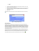

you will be presented with a confirmation dialog. You may select OK to proceed and delete the
logs or Cancel to exit without deleting the logs.
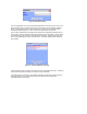
4.3.4 Generate Topology
This menu allows the user to document the network topology. It generates an HTML file that
contains the list of all the device name, address, type, properties, links and scenes. This list is
useful for troubleshooting the network or simply as a reference.
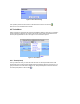
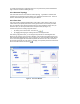
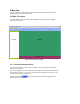
4.3.5 Floor Plan
This menu provides a graphical representation of the location of each device. It allows you to
create locations (rooms) and place devices in their physical location. This will help if at a later
time you would like to know where the specific device you are controlling is located. Once you
select this option you will be presented with the floor plan window (see Figure 17).
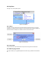
There are two options for creating a physical location:
i. By clicking on the “New Location” icon at the top (
).
ii. By dragging and dropping an existing scene from the Navigation Pane
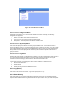
After creating a physical location, you can drag and drop devices from the Navigation Pane
directly into any location on the Floor Plan’s Window. Devices which are dropped into the Floor
Plan maintain their relationships and, as such, clicking on any of the controlling (master) devices
on the Floor Plan highlights the associated responders with the Floor Plan. Also, each device
has its state captured as part of its name (i.e. Hall1[off]). This operation performs the same action
as the Floor Plan button on the tool bar (
).
Figure 17. Floor Plan Window