
User Manual


Table Of Contents
- UAD Powered Plug-Ins
- Introduction
- UAD Installation
- Overview
- QuickStart DVD
- System Requirements
- Supported Hosts
- Latest Information & Software Updates
- UAD Software Installation
- Install Software First
- UAD Hardware Installation
- Authorization
- Authorize Plug-Ins Procedure
- Load Authorization File
- Offline Authorization
- Using Unlicensed Plug-Ins
- Verifying Installation
- Learn More
- Software Removal
- UAD System Overview
- My.uaudio.com
- Using Multiple UAD Cards
- UAD Meter & Control Panel
- Overview
- Launching the UAD Meter & Control Panel Application
- Using the UAD Meter
- UAD Meter Elements
- UAD Control Panel
- System Information Panel
- Plug-Ins Panel
- Configuration Panel
- Help & Support Panel
- Using UAD Powered Plug-Ins
- Tempo Sync
- UAD Delay Compensation
- UAD-Xpander & UAD-Xtenda
- LA-2A and 1176LN
- LA-3A Compressor
- Fairchild 670
- Precision Multiband
- Precision Limiter
- Precision Buss Compressor
- Neve 33609 Compressor
- VCA VU
- Neve 88RS Channel Strip
- CS-1 Channel Strip
- Precision Equalizer
- Cambridge EQ
- Pultec and Pultec-Pro
- Neve 1073 Equalizer
- Neve 1081 Equalizer
- Helios Type 69 Equalizer
- Roland CE-1
- Roland Dimension D
- Roland RE-201
- RealVerb Pro
- DreamVerb
- Plate 140
- Precision Maximizer
- Precision De-Esser
- Precision Enhancer kHz
- SPL Transient Designer
- Nigel
- Introducing Nigel
- Preflex Plug-in
- Preflex Modules
- Gate/Comp Module
- Amp Module
- Amp Controls
- Cabinet Module
- Phasor Module
- Mod Filter Module
- TremModEcho plug-in
- Trem/Fade Module
- Mod Delay Module
- Echo Module
- Moog Multimode Filter
- History
- Index
UAD Powered Plug-Ins Manual - 359 - Chapter 39: History
The basic concept of a compressor/limiter, is of course, relatively simple. It's a device in which
the gain of a circuit is automatically adjusted using a predetermined ratio that acts in response
to the input signal level. A compressor/limiter "rides gain" like a recording engineer does by
hand with the fader of a console: it keeps the volume up during softer sections and brings it
down when the signal gets louder. The dynamic processing that occurs at ratios below 10 or
12 to one is generally referred to as compression; above that it's known as limiting.
Modern day compressors offer a great degree of programmablity and flexibility--older devices
such as the 1176 and the LA-2A are more straightforward in their design. Perhaps it is this fact
that has contributed to their appealing sound and the longevity of their popularity.
LA-2A
The LA-2A leveling amplifier, a tube unit with hand wired components and three simple con-
trols, was introduced in the mid-1960s. It utilized a system of electro-luminescent optical gain
control that was quite revolutionary. Gain reduction was controlled by applying the audio volt-
age to a luminescent driver amplifier, with a second matched photoconductive cell used to con-
trol the metering section. With its 0 to 40 dB of gain limiting, a balanced stereo interconnec-
tion, flat frequency response of 0.1 dB from 30-15,000Hz and a low noise level (better than
70 dB below plus 10 dBm output), the LA-2A quickly became a studio standard. Originally pat-
ented by Jim Lawrence, it was produced by Teletronix in Pasadena, California, which became
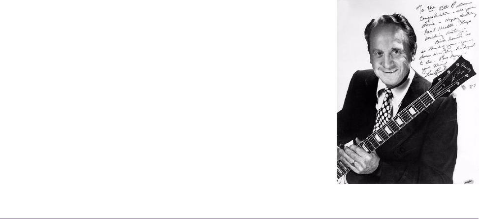
a division of Babcock Electronics Corporation in 1965. In 1967 Babcock's broadcast division
was acquired by the legendary Bill Putnam's company, Studio Electronics Corporation shortly
before he changed the company’s name to UREI®. Three different versions of the LA-2A were
produced under the auspices of these different companies before production was discontinued
around 1969.
1176LN
It was Bill Putnam himself who, in 1966, was responsible for the
initial design of the 1176. Its circuit was rooted in the 1108
preamplifier which was also designed by Putnam. As is evident
from entries and schematics in his design notebook, he experi-
mented with the recently developed Field Effect Transistor (F.E.T.)
in various configurations to control the gain reduction in the cir-
cuit. He began using F.E.T.s as voltage variable resistors, in which
the resistance between the drain and the source terminals is con-
trolled by a voltage applied to the gate. His greatest challenge
was to ensure that distortion was minimized by operating the
F.E.T.s within a linear region of operation.