
User Manual
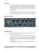


Table Of Contents
- UAD Powered Plug-Ins
- Introduction
- UAD Installation
- Overview
- QuickStart DVD
- System Requirements
- Supported Hosts
- Latest Information & Software Updates
- UAD Software Installation
- Install Software First
- UAD Hardware Installation
- Authorization
- Authorize Plug-Ins Procedure
- Load Authorization File
- Offline Authorization
- Using Unlicensed Plug-Ins
- Verifying Installation
- Learn More
- Software Removal
- UAD System Overview
- My.uaudio.com
- Using Multiple UAD Cards
- UAD Meter & Control Panel
- Overview
- Launching the UAD Meter & Control Panel Application
- Using the UAD Meter
- UAD Meter Elements
- UAD Control Panel
- System Information Panel
- Plug-Ins Panel
- Configuration Panel
- Help & Support Panel
- Using UAD Powered Plug-Ins
- Tempo Sync
- UAD Delay Compensation
- UAD-Xpander & UAD-Xtenda
- LA-2A and 1176LN
- LA-3A Compressor
- Fairchild 670
- Precision Multiband
- Precision Limiter
- Precision Buss Compressor
- Neve 33609 Compressor
- VCA VU
- Neve 88RS Channel Strip
- CS-1 Channel Strip
- Precision Equalizer
- Cambridge EQ
- Pultec and Pultec-Pro
- Neve 1073 Equalizer
- Neve 1081 Equalizer
- Helios Type 69 Equalizer
- Roland CE-1
- Roland Dimension D
- Roland RE-201
- RealVerb Pro
- DreamVerb
- Plate 140
- Precision Maximizer
- Precision De-Esser
- Precision Enhancer kHz
- SPL Transient Designer
- Nigel
- Introducing Nigel
- Preflex Plug-in
- Preflex Modules
- Gate/Comp Module
- Amp Module
- Amp Controls
- Cabinet Module
- Phasor Module
- Mod Filter Module
- TremModEcho plug-in
- Trem/Fade Module
- Mod Delay Module
- Echo Module
- Moog Multimode Filter
- History
- Index

UAD Powered Plug-Ins Manual - 215 - Chapter 23: Pultec and Pultec-Pro
In the hardware MEQ-5, the audio is still slightly colored even when the
switch is in the Out position and the peak/dip controls are at zero. This is due
to the fact that the signal is still passing through its circuitry. Because the plug-
in emulates the hardware in every regard, the signal will be slightly processed
when this switch is in the In position and the peak/dip controls are at zero. If
a true bypass is desired, use the host disable switch.
Low Peak Controls
Frequency
Selector Switch
This switch determines the frequency of the low-midrange portion of the equal-
izer. Five frequencies are available: 200Hz, 300Hz, 500Hz, 700Hz, and
1kHz.
Boost Knob This knob determines the amount of low-midrange “Peak” (gain) to be applied
to the frequency set by the low-midrange frequency selector.
Dip Controls
Frequency
Selector Switch
This switch determines the frequency of the midrange portion of the equalizer.
Eleven frequencies are available: 200Hz, 300Hz, 500Hz, 700Hz, 1kHz,
1.5kHz, 2kHz, 3kHz, 4kHz, 5kHz, and 7kHz.
Attenuation
Knob
This knob determines the amount of midrange “Dip” (cut) to be applied to the
frequency set by the midrange frequency selector.
High Peak Controls
Frequency
Selector Switch
This switch determines the frequency of the high-midrange portion of the
equalizer. Five frequencies are available: 1.5kHz, 2kHz, 3kHz, 4kHz, and
5kHz.
Boost Knob This knob determines the amount of high-midrange “Peak” (gain) to be ap-
plied to the frequency set by the high-mid frequency selector.
MEQ-5 Response Curves
We’ve included a few frequency response plots that illustrate the response
curves of the MEQ-5. All plots were taken at a sample rate of 192kHz.