
User Manual


Table Of Contents
- UAD Powered Plug-Ins
- Introduction
- UAD Installation
- Overview
- QuickStart DVD
- System Requirements
- Supported Hosts
- Latest Information & Software Updates
- UAD Software Installation
- Install Software First
- UAD Hardware Installation
- Authorization
- Authorize Plug-Ins Procedure
- Load Authorization File
- Offline Authorization
- Using Unlicensed Plug-Ins
- Verifying Installation
- Learn More
- Software Removal
- UAD System Overview
- My.uaudio.com
- Using Multiple UAD Cards
- UAD Meter & Control Panel
- Overview
- Launching the UAD Meter & Control Panel Application
- Using the UAD Meter
- UAD Meter Elements
- UAD Control Panel
- System Information Panel
- Plug-Ins Panel
- Configuration Panel
- Help & Support Panel
- Using UAD Powered Plug-Ins
- Tempo Sync
- UAD Delay Compensation
- UAD-Xpander & UAD-Xtenda
- LA-2A and 1176LN
- LA-3A Compressor
- Fairchild 670
- Precision Multiband
- Precision Limiter
- Precision Buss Compressor
- Neve 33609 Compressor
- VCA VU
- Neve 88RS Channel Strip
- CS-1 Channel Strip
- Precision Equalizer
- Cambridge EQ
- Pultec and Pultec-Pro
- Neve 1073 Equalizer
- Neve 1081 Equalizer
- Helios Type 69 Equalizer
- Roland CE-1
- Roland Dimension D
- Roland RE-201
- RealVerb Pro
- DreamVerb
- Plate 140
- Precision Maximizer
- Precision De-Esser
- Precision Enhancer kHz
- SPL Transient Designer
- Nigel
- Introducing Nigel
- Preflex Plug-in
- Preflex Modules
- Gate/Comp Module
- Amp Module
- Amp Controls
- Cabinet Module
- Phasor Module
- Mod Filter Module
- TremModEcho plug-in
- Trem/Fade Module
- Mod Delay Module
- Echo Module
- Moog Multimode Filter
- History
- Index
UAD Powered Plug-Ins Manual - 138 - Chapter 14: Precision Multiband
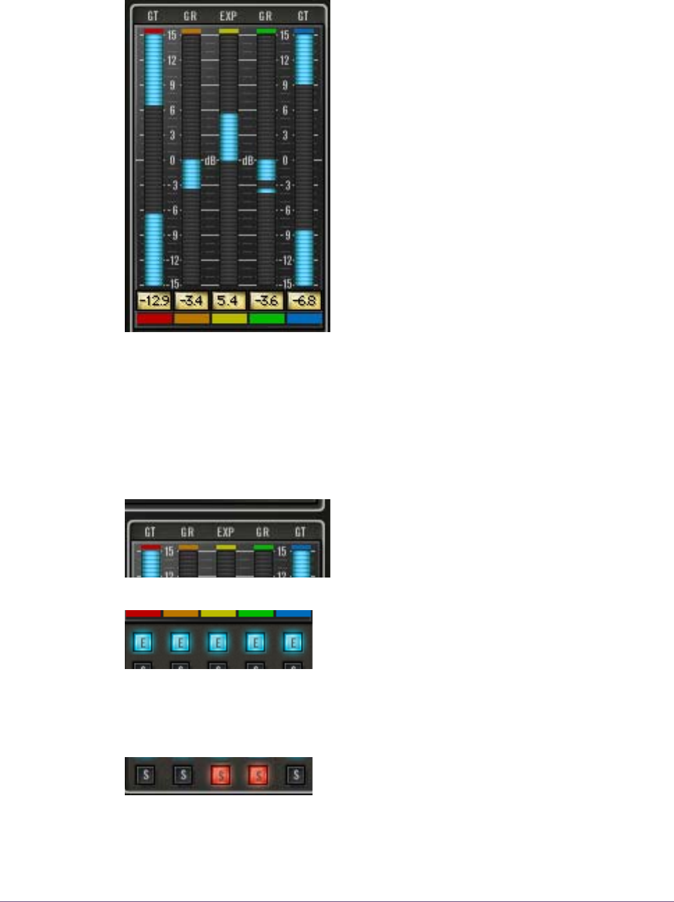
Dynamics Meters
Realtime display of Precision Multiband dy-
namics processing is shown in the Dynamics
Meters. This area also contains the band en-
able and band solo controls.
There is one vertical dynamics meter for each
band. They are color coded to match the
bands, and represent (from left to right) the LF,
LMF, MF, HMF, and HF bands respectively. Dy-
namics processing for each band is indicated
by light blue “LED-style” metering.
Zero dB is at the center of the meter, and the
range is ±15dB. Downward/negative meter-
ing indicates compression is occurring on the
band. Upward/positive metering indicates ex-
pansion is occurring.
In Gate mode, there is simultaneous inward metering from the top and bottom
to the center, which provides a visual “gate” that opens and closes along with
the gate processing.
Dynamics Meters signal peaks are held for 3 seconds before resetting.
Meter Labels The labels above the Dynamics Meters reflect
the mode that each band is in: GR (Gain Re-
duction) for compression, EXP for expansion,
and GT for Gate.
Band Enable
Buttons
Each band has an Enable button. The Enable but-
ton for the band is just below its dynamics meter.
The band is active when its Enable button is light
blue. Click the button to toggle the active state of the band. Disabling bands
does not reduce UAD CPU usage.
Band Solo
Buttons
Each band has a Solo button. The Solo button for
the band is just below its Enable button.
When one or more bands are in Solo mode, only the soloed bands can be
heard and the other bands are muted.