
User Manual
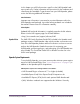


Table Of Contents
- UAD Powered Plug-Ins
- Introduction
- UAD Installation
- Overview
- QuickStart DVD
- System Requirements
- Supported Hosts
- Latest Information & Software Updates
- UAD Software Installation
- Install Software First
- UAD Hardware Installation
- Authorization
- Authorize Plug-Ins Procedure
- Load Authorization File
- Offline Authorization
- Using Unlicensed Plug-Ins
- Verifying Installation
- Learn More
- Software Removal
- UAD System Overview
- My.uaudio.com
- Using Multiple UAD Cards
- UAD Meter & Control Panel
- Overview
- Launching the UAD Meter & Control Panel Application
- Using the UAD Meter
- UAD Meter Elements
- UAD Control Panel
- System Information Panel
- Plug-Ins Panel
- Configuration Panel
- Help & Support Panel
- Using UAD Powered Plug-Ins
- Tempo Sync
- UAD Delay Compensation
- UAD-Xpander & UAD-Xtenda
- LA-2A and 1176LN
- LA-3A Compressor
- Fairchild 670
- Precision Multiband
- Precision Limiter
- Precision Buss Compressor
- Neve 33609 Compressor
- VCA VU
- Neve 88RS Channel Strip
- CS-1 Channel Strip
- Precision Equalizer
- Cambridge EQ
- Pultec and Pultec-Pro
- Neve 1073 Equalizer
- Neve 1081 Equalizer
- Helios Type 69 Equalizer
- Roland CE-1
- Roland Dimension D
- Roland RE-201
- RealVerb Pro
- DreamVerb
- Plate 140
- Precision Maximizer
- Precision De-Esser
- Precision Enhancer kHz
- SPL Transient Designer
- Nigel
- Introducing Nigel
- Preflex Plug-in
- Preflex Modules
- Gate/Comp Module
- Amp Module
- Amp Controls
- Cabinet Module
- Phasor Module
- Mod Filter Module
- TremModEcho plug-in
- Trem/Fade Module
- Mod Delay Module
- Echo Module
- Moog Multimode Filter
- History
- Index

UAD Powered Plug-Ins Manual - 110 - Chapter 11: LA-2A and 1176LN
Figure 26 depicts the input and output characteristics of a compressor and
perfect amplifier. When operated within its specified range, an amplifier pro-
vides a constant amount of gain regardless of the input signal level. In
Figure 26, the signal level of a perfect amplifier is represented with a constant
output gain of 10 dB. In this example, a signal with an input level of –30 dB
results in an output level of –20 dB, which is an increase of 10 dB. Similarly,
an input level of 0 dB results in an output level of 10 dB (the gain stays fixed
at 10 dB regardless of the input level).
In contrast to an amplifier, whose function is to present a constant gain, a
compressor varies its gain in response to the level of the input signal. Large in-
put signals result in less gain, thus reducing or compressing the dynamic
range of the signal. In Figure 26, a compressed signal with an input level of
–30 dB results in an output level of –20 dB, indicating a gain of 10 dB. How-
ever, with input levels of –20 dB and –10 dB, the compressor exhibits gains
of 5 dB and 0 dB (respectively), thereby illustrating that the gain decreases as
the input signal increases. This increase in output level by 5 db for every
10 dB is defined as a compression ratio of 2:1 (reduced from 10:5).
The amount of compression, or gain reduction, typically expressed
in decibels (dB), is defined as the amount by which the signal level is reduced
by the compressor. Graphically, this can be represented (see Figure 27) by
the difference in output levels between the original signal (without compres-
sion) and the compressed signal. The LA-2A and 1176LN display this value
when their VU Meters are set to Gain Reduction.
Figure 26. Input and output characteristics of a compressor and perfect amplifier
–20
–10
0
+10
+10
–30
–10
–30 –20 0
Perfect
Amplifier
Compression
Output
Level (dB)
Input Level (dB)