
Installation manual


UT340, UT360, UT380, and UT3100
Planning and Installation Manual
16
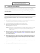
X005
X004 X003
COM-PORT
X001
To Controller
Not Used
COMMUNICATION
INTERFACE BOARD
X002
X003 25 PIN SUB D MALE
X004 25 PIN SUB D MALE
X005 25 PIN SUB D FEMALE
Serial Port
0 - 20 mA current loop
Serial Port
RS232
RELAY CONTACTS: 30 VAC, 60 VDC
Maximum 0.5 A, Minimum 0.05 mA
14
15 “UPS on” (shown with UPS off)
2
16
17 “Static bypass operation” (shown with static bypass operation off)
4
18
19 “Battery operation” (shown with battery operation off)
6
20
21 “Battery low warning” (shown with “battery low” warning off)
8
13 + Remote UPS shut down input (3.5 - 25 VDC pulse for 1 second minimum)
25 –
Figure 7: Communication Interface Board (Option)
Use Class 1 wiring methods.