
Installation manual


UT340, UT360, UT380, and UT3100
Planning and Installation Manual
14
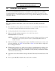
Figure 5: UT380 and UT3100 Installation Wiring Diagram, Typical Installation
NOTE 1:
Size the mains input overcurrent protection
device per applicable codes. See the table below for
mains input volta
g
e and current ratin
g
s.
Mains Input
UPS Model VAC Maximum Amps
UT380 480 173
UT3100 480 216
NOTE 2:
(a) Refer to an
y
instructions provided with the
DC disconnect (DCD) and pre-char
g
e/dischar
g
e box.
(b) The pre-char
g
e/dischar
g
e box must be located less
than 10 feet (3 meters) from the DC disconnect.
ADDITIONAL NOTES:
A qualified electrician must install the UPS accordin
g
to all applicable codes.
All power and control wires must be in separate
conduits.
If
y
ou do not have a BEST-supplied maintenance
b
y
pass cabinet (MBC),
y
ou must provide overcurrent
protection and UPS input AC disconnect means.