
Installation manual


UT340, UT360, UT380, and UT3100
Planning and Installation Manual
12
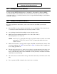
Figure 3: UT340 - UT3100 Installation Wiring Diagram, Typical Installation,
No External Maintenance Bypass Cabinet
NOTE 1:
(a) For a UT340 or UT360, see Table 1 in
Section 102 for recommended input overcurrent
protection. (b) For a UT380 or UT3100, see Table 5 in
Section 103 for recommended input overcurrent
protection.
NOTE 2:
(a) For a UT340 or UT360, see Table 2 in
Section 102 for recommended output overcurrent
protection. (b) For a UT380 or UT3100, see Table 6 in
Section 103 for recommended output overcurrent
protection.
NOTE 3:
You must provide overcurrent protection and
UPS input AC disconnect means.
NOTE 4:
(a) Refer to an
y instructions provided with the
DC disconnect (DCD) and pre-charge/discharge switch.
(b) The pre-char
ge/discharge box must be located less
than 10 feet (3 m) from the DC disconnect.
ADDITIONAL NOTES:
A qualified electrician must install the UPS accordin
g
to all applicable codes.
All power and control wires must be in separate
conduits.
The
grounding electrode conductor (protective
earth—PE) must be the same size (ampacit
y) as the
UPS input conductors. Conduit is not an acceptable
grounding electrode conductor—see National Electrical
Code Section 250-91(a).
A UT340 or UT360 unit is wired from the factor
y as a
separatel
y derived system. Output neutral is bonded to
equipment
ground through main bonding jumper inside
the UPS. See National Electrical Code Article 250-5(d)
and 250-26 for proper installation
grounding.