
User's Manual

CAC 5
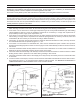
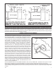
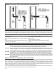
FIGURE 5 - FLOOR PROTECTION
FLOOR PROTECTION
This heater has been designed to prevent excessive temperatures on the fl oor beneath the heater. It is important, however, that a
combustible fl oor be protected by a 3/8 inch minimum thick noncombustible inorganic millboard having a thermal conductivity of k=0.43
BTU/ft.
2
/in./hr./°F or a listed fl oor protector beneath the heater extending beyond the heater as shown by fi gure 5. The fl oor covering
is required to prevent damage or possible ignition from sparks or glowing embers that might escape the heater during refueling or
ash removal or drop from the joints of the chimney connector.
CHIMNEY CONNECTOR AND CHIMNEYS
It is very important to assure safe and satisfactory performance from
your heater that it be properly connected to a correctly constructed
and maintained chimney. If a Listed High Temperature Type HT
Factory-Built Residential and Building Heating Appliance Chimney
is used, follow the chimney manufacturer’s installation instruc-
tions carefully. If a masonry chimney is to be used, be sure it is
constructed to the National Fire Protection Association (N.F.P.A)
and local code standards. A copy of the N.F.P.A 211 Chimney,
Fireplaces, Vents and solid Fuel Burning Appliances may be ob-
tained from N.F.P.A., Inc. Batterymarch Park, Quincy, MA 02269.
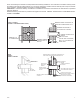
The Chimney connector (pipe from heater to chimney) must be 6 inches
in diameter and made from 24 gauge or heavier steel. The length of the
chimney connector and number of elbows* used should be kept to a
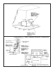
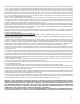
minimum. Moisture that might collect in the chimney should be directed
to the heater by providing a slope of 1/4 inch per foot in a horizontal run
of the chimney connector and installing all pipes with the crimped end
toward the heater, (See fi gure 6). The chimney connector should extend
at least two inches into the fl ue of a factory-built chimney. When mak-
ing a horizontal connection to a masonry chimney, the connector should
extend to the inside face of the vertical fl ue liner, (see fi gures 7 and 8).
When connecting the heater to a masonry fi replace, the chimney connector
should extend into the chimney’s liner as shown by the side section view
of fi gure 4. All chimney connector joints should be sealed with furnace
cement and secured with No. 8 sheet metal screws as described by the
TO SAFELY AND PROPERLY INSTALL THIS HEATER section of this
manual. *Use Corrugated Elbows.
DO NO USE MORE THAN TWO 90 DEGREE ELBOWS IN THE Chimney CONNECTOR. Installations which require two degree
elbows must be vented into a fl ue of at least 8” diameter or 8” square to prevent chimney draft restrictions, (see fi gure 2).
DO NOT PASS A CHIMNEY CONNECTOR THROUGH A FLOOR OR CEILING OF ANY KIND. Only Listed Factory-Built Residential
Type and Building Heating Appliance Chimneys or masonry chimneys constructed to N.F.P.A. standards should pass through a fl oor
or ceiling.
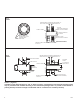
PIPE ANGLE UP
HORIZONTAL
TO HEATER
FIGURE 6 - RISE OF HORIZONTAL
CHIMNEY CONNECTOR PIPE
TO CHIMNEY
RISE:
1/4” FOR EACH FOOT
OF CONNECTOR
LENGTH