MS860 WiFi Bar Code Scanner REV.
TABLE of CONTENTS Introduction . . . . . . . . . . . . Introduction . . . . . . . . . . . Quick Start . . . . . . . . . . . Scanner Parts . . . . . . . . . . Cradle Parts . . . . . . . . . . . Charging the Scanner . . . . . . . Network Settings . . . . . . . . . . Introduction . . . . . . . . . . . Modifying the WiFi Settings . . . . . Glossary . . . . . . . . . . . . Network Setting . . . . . . . . . . with Scanner Configuration Manager with Bar Codes . . . . . . . . Install Virtual COM . . . . . . . . .
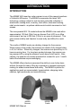
INTRODUCTION INTRODUCTION The MS860 WiFi laser bar code scanner is one of the newest members of Unitech’s MS series. The MS860 incorporates the latest WiFi technology, making it ideal for real-time bar code data collection in warehouse, loading dock, inventory, back office, document tracking, retail environments - anywhere cables would restrict movement or limit access. The incorporated 802.
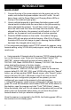
INTRODUCTION QUICK START 1. Connect the plug of the power adapter into the power jack on the cradle, and connect the power adapter into an AC outlet. You will hear a beep, and the Power Status and Charging Status LEDs on the top of the cradle will glow green. 2. Use an unfolded paperclip to push down the battery power on/off internal switch located inside the round hole on the yellow warning label underneath the scanner.
INTRODUCTION IMPORTANT NOTES “ACK” helps avoid data loss during an Access Point (AP) power disconnection. To turn “ACK” on, follow the steps below: Print out pg.65 - RS232 Settings Scan: Enter Group 4 C5 1 Exit After “ACK” is turned on, the scan data transmission rate might be a little slower, depending on your wireless network condition.
INTRODUCTION SCANNER AND ACCESSORIES: IMPORTANT NOTES “ACK” helps avoid data loss during an Access Point (AP) power MS860-W8A: MS860 WiFi“ACK” laser scanner w/US plug below: disconnection. To turn on, follow the steps MS860-W8B: MS860 WiFiD.
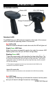
INTRODUCTION SCANNER PARTS: Status LED ON / OFF Switch Buzzer Charge Contacts Trigger Scanner LED The MS860 has one LED indicator located on the head of the scanner which indicates the operating status of the scanner. Red LED is ON When the scanner attempts to read a bar code, the LED will glow red. Single Green LED Flash When the scanner successfully reads a bar code the scanner LED flashes green once, and you will hear a single beep.
INTRODUCTION Buzzer The MS860 provides audible feedback while it is in operation. These sounds indicate the operating status of the scanner. One High Tone Beep The scanner will beep once after successfully reading a bar code. One High-Low-High Beep After scanning a ‘begin configuration’ bar code (“Enter Group 5”, for instance), the scanner LED will flash green while the scanner simultaneously gives one high-low-high tone beep.
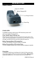
INTRODUCTION CRADLE PARTS: Power On / Off LED Battery Charging LED Charge Contacts Power Plug Cradle LEDs The MS860 charging cradle has two LED indicators (power on/off status and battery charging status). Power ON/OFF Status LED stays ON When the power adapter plug is connected into the power jack on the cradle, and the power adapter is connected into an AC outlet, the cradle will beep, and the LED on the top of the cradle will remain on.
INTRODUCTION CHARGING THE SCANNER: Prior to performing any operation with the scanner, make sure it has been fully charged. How to determine if the scanner needs recharging: 1. During operation, a flashing red scanner LED indicates the scanner has low power. 2. When the trigger is pressed and a scan laser line is not visible (do NOT look directly into the scanner), the scanner has no power. Make sure the scanner is not merely switched off. To charge the scanner, place the unit into the cradle.
NETWORK SETTINGS INTRODUCTION The MS860 WiFi is designed to connect to your computer(s) via the existing wireless network through one of its Access Points (APs), thereby eliminating the dedicated wireless receiving unit required by other types of wireless scanners. Integrating the MS860 into the wireless network is the same as integrating any other piece of wireless hardware, requiring that you give it its own unique IP address, which can be obtained from your network administrator.
NETWORK SETTINGS So, two things must be configured: the MS860’s Wireless Network settings, and the host computer’s Virtual Com Port settings. Consult your network administrator for the appropriate network wireless settings for your MS860 which must be manually configured via Scanner Configuration Manager or bar codes (see below and pages 31 to 60). VCOM should automatically create a “virtual com port” for the Access Point to communicate data through.
NETWORK SETTINGS GLOSSARY IP Address IP Address (short for Internet Protocol) is simply four numbers (like 192.168.1.250) separated by periods that is used to identify a particular device within a network, just as an employee number is used to identify an individual person within a company. The IP Address can either be automatically assigned by the wireless network or manually assigned by the user.
NETWORK SETTINGS WEP WEP (Wireless Encryption Protocol) is a security key for communicating with an access point. If the correct key is not presented, communication is denied. Because WEP is used for security reasons, it must be obtained from your Network Administrator.
NETWORK SETTINGS NETWORK SETTINGS There are two methods to configure your scanner to its IP settings (obtained from your Network Administrator) - via Scanner Configuration Manager (SCM) and via manual bar code scanning. SCM has the advantage in that it’s quick and easy, and works for most situations. Direct bar code scanning (starting on page 17) offers full “hands on” control over your MS860’s IP settings, but can be tedious.
NETWORK SETTINGS Step 3: Fill in the SSID name of the Access Point (AP). Click “Next”. Step 4: Select wireless network type. Step 5: Select “Yes” for DHCP on, “No” for DHCP off. Step 6: If DHCP “Off” is selected, fill in the IP Address, Subnet Mask, and Gateway. Click “Next”. Step 7: Select whether your wireless network is using WEP encryption for data security. Click “Next”.
NETWORK SETTINGS Step 8: If “Yes” was selected in Step 7, fill in the WEP parameters and type a passwork in the Key 1 field. Click “Next”. Step 9: Select “Yes” or “No” for Power Saving Mode. Step 10: Verify the information is correct. Click “Back” to modify the configuration if necessary. Click “Next” when finished. Step 11: Setup is complete. Step 12: Select an appropriate printer to produce a setup sheet containing bar codes.
NETWORK SETTINGS IMPORTANT: Once you have completed the network configuration for the scanner, VCOM will be required to configure the virtual com port, which means the VCOM utility must run in the background. This is detailed on pages 21 to 24. Some Access Points may not be able to re-connect to the MS860 after it’s been out of range. In this case the scanner will need to be powered off and powered on again, and the VCOM communication must be re-started. VCOM Utility supports Windows2000 and XP.
NETWORK SETTINGS USING BAR CODES TO SET SCANNER NETWORK: The WLAN default settings are shown below. WLAN Default Settings: Item IP Address IP Subnet Mask Gateway IP Address SSID RF Channel WEP Authentication Type Default Setting 192.168.1.250 255.255.255.0 192.168.1.254 Wlandemo 6 Disabled Auto Use the TCP/IP barcode chart on page 81 and the ASCII Chart on pages 83 to 86 to configure your scanner to your own network settings, as the example below: SSID: MySSID IP: 192.168.1.100 Mask: 255.255.255.
NETWORK SETTINGS General Command List: MODE SSID CHAN PSMODE WEP DEFAULT SAVE EXIT SE BAUD AA WK WKID IP MASK GW DHCP , Set network mode , Set SSID <1 - 14>, Set channel <1 / 0>, PS mode ON/OFF <1 / 0>, WEP ON/OFF Restore configuration to factory default Save configuration to flash Save configuration to flash Save and exit configuration <0 / 1 / 2 / 3>, Set RS232 Baudrate , Set Authentication Algorithm <1 - 4> <1 - 4>, Set WEP
NETWORK SETTINGS 7. WEP Turn WEP on or off Example: WEP Space 1 CR (turn on WEP) Example: WEP Space 0 CR (turn off WEP) 8. WKID Set which WEP key that you want to use, of which you have four. Example: WKID Space 1 CR (use WEP key number 1) Example: WKID Space 2 CR (use WEP key number 2) Example: WKID, Space 3 CR (use WEP key number 3) Example: WKID Space 4 CR (use WEP key number 4) 9. WK Set WEP key association with a WEP key number.
NETWORK SETTINGS 13. SAVE Save the configuration settings Example: SAVE CR 14. SE Save the configuration settings and reboot Example: SE CR 15. DEFAULT Restore configuration settings to factory default, and automatically reboot the module Example: DEFAULT CR 16.
NETWORK SETTINGS After you have configured your MS860’s IP settings, follow the steps below and on the next page to install and start VCOM. VCOM establishes a “virtual com port” on your host computer that coordinates with your MS860’s IP address. INSTALLING VIRTUAL COM Step 1: Install VCOM utility from the User Guide CD, or use your CD browser and doubleclick Setup.exe to install VCOM. Step 2: Click “Next”, and then select the directory into which you would like VCOM installed.
NETWORK SETTINGS Step 4: Click “Next” and confirm information. The installation procedure will start automatically. Step 5: Click “Finish” to complete the installation process.
NETWORK SETTINGS START VIRTUAL COM: Step 1: Start the Virtual Com utility from the Icon Tray. Click the “Config” button. Step 2: Set the virtual com port associated with the corresponding IP address to your wireless module. Click the “Add” button to add a VCOM = IP pair to the list on the right. Click the “OK” button. Step 3: Click the Start (“Star”) button to start the virtual com communication with your wireless module.
NETWORK SETTINGS Step 4: Click the “Search” button. The found wireless device will be added to the IP List panel. IMPORTANT: Once you have completed the network configuration for the scanner (pages 13 to 17), VCOM will be required to configure the virtual com port, which means the VCOM utility must run in the background. Some Access Points may not be able to re-connect to the MS860 after it’s been out of range.
NETWORK SETTINGS Using Monitor.exe for scannerthe network So, two things must be configured: MS860’ssetting Wireless Network settings, and the host computer’s Virtual Com Port settings. Consult your network administrator (Monitor.exe is available from Unitech)for the appropriate network wireless settings for your MS860 which must be manually configured viausing Scanner Configuration or barplease codes install (see below 1. Before the monitor.exe forManager configuration, Vcom andinpages 12 first. to 19).
NETWORK SETTINGS GLOSSARY IP Address IP Address (short for Internet Protocol) is simply four numbers (like 192.168.1.250) separated by periods that is used to identify a particular device within a network, just as an employee number is used to identify an individual person within a company. The IP Address can either be automatically assigned by the wireless network or manually assigned by the user.
NETWORK SETTINGS Configure the virtual com port using monitor.exe: WEP WEP (Wireless Encryption Protocol) is a security key for communicating with access point. Select If the correct is not 1. On monitor.exe, clickan “Configuration. “Virtualkey COM”. presented, communication is denied. Because WEP is used for security reasons, it must be obtained from your Network Administrator.
NETWORK SETTINGS 4. Keep the default settings of the server port and server IP. NETWORK SETTINGS There Note are two methods to configure your scanner to its IP settings (obtained from your Network Administrator) - via Scanner Configuration Manager manual bar code scanning. has the 1. The PC(SCM) whichand run via moniter.exe utility should detectSCM the IP address advantage in that it’s quick and easy, and works for most situations. itself and the IP address should be act as TCP server.
NETWORK SETTINGS Scan send data WiFi: Step 3: data Fill inand the SSID name of via the Access Point (AP). Click “Next”. 1. After you have set the network configuration for your scanner and set the virtual com port, you are ready to scan data and transmit them to your server thru the WiFi. 2. When your scanner connected to the WLAN, the flashing green LED on the scanner turnnetwork into steady Step 4: Select wireless type.green. 3.
NETWORK SETTINGS 5. Define RS232 settings according to page 88, RS232 Default Step 8: Ifthe “Yes” was selected in Step 7, fill in Settings,the click “OK” WEP parameters and type a passwork in the Key 1 field. Click “Next”. Step 9: Select “Yes” or “No” for Power Saving Mode. 6. Press the scan button to scan the barcode. Step 10: Verify the information is correct. Click “Back” to modify the configuration if necessary. Click “Next” when finished. Step 11: Setup is complete.
SCANNER CONFIGURATION MANAGER Scanner Configuration Manager software is the simplest and most foolproof way to configure your scanner settings. Start It Up After loading and starting SCMSetup.exe, the icon to the right will appear on your desktop: Click on the SCM icon and the screen to the right appears: As you can see, you are presented with a blank work area and a row of icons across the top.
SCANNER CONFIGURATION MANAGER The above four icons are used in the “Data Editing” feature of SCM. From left to right they are the “Add a Formula” icon, the “Remove a Formula” icon, and the right-hand two are the “Move Formula” icons that move selected formulas up or down in relation to each other. For information on data editing, see page 78. Click this icon to print a series of bar codes that you can scan in order to configure your scanner to the current SCM settings.
SCANNER CONFIGURATION MANAGER Try It! Click the SCM Icon, if you haven’t already done so. Two work areas appear with a row of icons along the top. Click the icon furthest to the left (new file). The screen to the right appears. Click on any of the selections under “Current Settings” to view its “Attributes”. Double-click on any of the “Attributes” to edit that attribute. This is done via a drop-down menu.
SCANNER CONFIGURATION MANAGER Using SCM for scanner network setting: Settings Step 1: Install SCM program from user guide CD and double click the scanner configuration on the Following is a detailed manager discussionicon of each ofdesktop the settings, their attributes, and the effects each of these will have on data output from your MS860. Beeps and Delays The three attributes for “Beeps and Delays” are: “Beep Tone”, “Interblock Delay”, and “Intercharacter Delay”.
SCANNER CONFIGURATION MANAGER Step 3: Fill in the SSID name of access point (AP) and click on “Next” Keyboard Wedge, continued button Function Code Function Code determines how function code characters from the MS860 are output. If Yes is selected, then scanned function codes will output as if their corresponding function keys were pressed. For instance scanning an F1 label will display a “Help” pop-up box, F3 will display a “Find” pop-up box, etc.
SCANNER CONFIGURATION MANAGER Step 5: Select DHCP on or off. RS232 “No” for DHCP off. Click “Yes” for DHCP on and click The RS232 input characteristics of the MS860 can be modified according to the following nine parameters: Baud Rate Baud Rate (bits per second) refers to the speed of the data from the MS860. Normally, the baud rate of the host RS232 port should match that of the input device. Default is “9600 Baud”.
SCANNER CONFIGURATION MANAGER Step 7: Select “Yes” or “No” if your wireless network using WEP RS232, continued encryption for data security or not, click “Next”. BCC Character Block Check Character. An error checking character added for data integrity. Default is “No”. Time Out The ACK/NAK function (see previous page) can be given a limited time (from 1 to 10 seconds) or an unlimited time to operate. Default is “1 Second”.
SCANNER CONFIGURATION MANAGER Step 9: Select “YES” for using power saving mode. Click “Next”. Scanner Port Scanner Port parameters refer to scanner functions (such as Double Verification, Scanning Mode, etc.) and some simple data editing features. For more powerful data editing, refer to the Data Editing section starting on page 44. Terminator The Terminator is a command that follows the input of bar code data.
SCANNER CONFIGURATION MANAGER Step 11: You will see the screen for finished Wi-Fi Setup wizard Scanner Port, continued Use Code ID Codabar The Code ID function can be used to Code 11 / Telpen identify the type of bar code that is being Code 32 scanned by inserting an identifying letter Code 39 (refer to the chart at right) at the beginCode 93 ning of the bar code input.
SCANNER CONFIGURATION MANAGER Settings Following is a detailed discussion of each of the settings, their attributes, and the effects each of these will have on data output from your MS860. Beeps and Delays The three attributes for “Beeps and Delays” are: “Beep Tone”, “Interblock Delay”, and “Intercharacter Delay”. Beep Tone Select a value from “None” to “High” to set the loudness of the tone, or select “Low to High” or “High to Low” to set the characteristic of the tone. Default is “Medium”.
SCANNER CONFIGURATION MANAGER Keyboard Wedge, continued Function Code Function Code determines how function code characters from the MS860 are output. If Yes is selected, then scanned function codes will output as if their corresponding function keys were pressed. For instance scanning an F1 label will display a “Help” pop-up box, F3 will display a “Find” pop-up box, etc. If No is selected, the scanned function codes will output special character strings defined by Unitech for non-print character output.
SCANNER CONFIGURATION MANAGER RS232 The RS232 input characteristics of the MS860 can be modified according to the following nine parameters: Baud Rate Baud Rate (bits per second) refers to the speed of the data from the MS860. Normally, the baud rate of the host RS232 port should match that of the input device. Default is “9600 Baud”. Parity Parity is an archaic technique used to detect data transmission errors by adding an extra bit to each character.
SCANNER CONFIGURATION MANAGER RS232, continued BCC Character Block Check Character. An error checking character added for data integrity. Default is “No”. Time Out The ACK/NAK function (see previous page) can be given a limited time (from 1 to 10 seconds) or an unlimited time to operate. Default is “1 Second”. Data Direction Three options are available for data direction: Send to Host Send to Host & Terminal Send to Terminal Default is “Send to Host”.
SCANNER CONFIGURATION MANAGER Scanner Port Scanner Port parameters refer to scanner functions (such as Double Verification, Scanning Mode, etc.) and some simple data editing features. For more powerful data editing, refer to the Data Editing section starting on page 57. Terminator The Terminator is a command that follows the input of bar code data.
SCANNER CONFIGURATION MANAGER Scanner Port, continued Use Code ID The Code ID function can be used to identify the type of bar code that is being scanned by inserting an identifying letter (refer to the chart at right) at the beginning of the bar code input. For example: if the Code ID function is on, and a bar code string of “54321” was output as “M54321”, the bar code would thus be identified as type Code 39. Default is “No”.
SCANNER CONFIGURATION MANAGER Scanner Port, continued Scanning Mode Scanning mode refers to the method by which scans are initiated, whether by pressing a trigger, or simply presenting a bar code to a continuously reading scanner. Scanning can occur in seven different ways: z Trigger scan causes the scanner light to remain on as long as the trigger is depressed, whether the bar code is recognized or not.
SCANNER CONFIGURATION MANAGER Scanner Port, continued Aim Function for Long Range Engine The Aim function causes a laser scanner to output a “pin-point” aiming aid for a specified period of time (see below) to enable a user to more easily scan distant bar code labels. Default is “No”. Aiming Time for Long Range Engine The Aiming Time function specifies the duration of the Aim Function (see above) The length of duration can be specified from 500ms to 2 seconds, in half-second increments.
SCANNER CONFIGURATION MANAGER Bar Code Symbologies Modify the output characteristics of 16 of the most popular bar code symbologies in current use. Following are the bar code symbologies and their modifiable parameters. Code 39 z Enabled toggles the ability for the scanner to read Code 39 on or off. Default is “Yes”. z Code ID (Standard) is a user-definable identification letter for z z z z z z Standard Code 39, which is referred to in the “Use Code ID” function on page 45. Default is letter “M”.
SCANNER CONFIGURATION MANAGER Bar Code Symbologies, continued Interleaved 2 of 5 z Enabled toggles the ability for the scanner to read I 2 of 5 on or off. Default is “Yes”. z Code ID is a user-definable identification letter for I 2 of 5, which is z z z z z 49 referred to in the “Use Code ID” function on page 45. Default is letter “I”. Fix Length (by first 3 reads) fixes the length of acceptable subsequent bar code reads from the first three bar codes read.
SCANNER CONFIGURATION MANAGER Bar Code Symbologies, continued Standard 2 of 5 / Toshiba Code (China Postal Code) z Enabled toggles the ability for the scanner to read S 2 of 5 / Toshiba z z z z z z Code on or off. Default is “No”. S25 Code ID is a user-definable identification letter for S 2 of 5, which is referred to in the “Use Code ID” function on page 45. Default is letter “H”. Toshiba Code ID is the same as S25 Code ID (above) but instead applicable to Toshiba Code. Default is letter “C”.
SCANNER CONFIGURATION MANAGER Bar Code Symbologies, continued Code 32 z Enabled toggles the ability for the scanner to read Code 32 on or off. Default is “No”. z Code ID is a user-definable identification letter for Code 32, which is referred to in the “Use Code ID” function on page 45. Default is letter “T”. z Send Leading Character toggles sending or not sending a leading (‘start bar code’) character. Default is “Send”.
SCANNER CONFIGURATION MANAGER Bar Code Symbologies, continued MSI / Plessey Code z Enabled toggles the ability for the scanner to read MSI / Plessey z z z z z z Code on or off. Default is “Yes”. MSI Code ID is a user-definable identification letter for MSI Code, which is referred to in the “Use Code ID” function on page 45. Default is letter “O”. Plessey Code ID is the same as MSI Code ID (above) but instead applicable to Plessey Code. Default is letter “P”.
SCANNER CONFIGURATION MANAGER Bar Code Symbologies, continued Codabar z Enabled toggles the ability for the scanner to read Codabar on or off. Default is “Yes”. z Code ID is a user-definable identification letter for Codabar, which is z z z z z referred to in the “Use Code ID” function on page 45. Default is letter “N”. Send Start/Stop toggles sending or not sending start/stop sentinels. Default is “No Send”.
SCANNER CONFIGURATION MANAGER Bar Code Symbologies, continued UPC-E z Enabled toggles the ability for the scanner to read UPC-E on or off. Default is “Yes”. z Code ID is a user-definable identification letter for UPC-E, which is z z z z referred to in the “Use Code ID” function on page 45. Default is letter “E”. Send Leading Digit toggles sending or not sending a leading (‘start bar code’) digit. Default is “Send”. Send Check Digit toggles sending or not sending a check digit. Default is “Send”.
SCANNER CONFIGURATION MANAGER Bar Code Symbologies, continued EAN-8 z Enabled toggles the ability for the scanner to read EAN-8 on or off. Default is “Yes”. z Code ID is a user-definable identification letter for EAN-8, which is referred to in the “Use Code ID” function on page 45. Default is letter “FF”. z Send Leading Digit toggles sending or not sending a leading (‘start bar code’) digit. Default is “Send”. z Send Check Digit toggles sending or not sending a check digit. Default is “Send”.
SCANNER CONFIGURATION MANAGER Bar Code Symbologies, continued Supplement Code (for UPC-E, ISBN, EAN-13) z Two Supplement Code toggles whether the two digit supplemental bar code is to be recognized. Default is “No”. z Five Supplement Code toggles whether the five digit supplemental bar code is to be recognized. Default is “No”. z Must Present toggles whether or not the supplemental bar code must be present in order to output data. Default is “Yes”.
SCANNER CONFIGURATION MANAGER Data Editing Data Editing is a powerful function that can give you tremendous control over how data is exported from the MS860. After clicking on “Data Editing” the data editing icons become active. Click on the icon with the blue circle and white plus sign. The “Define Formula” pop-up box to the right appears, which is divided into two sections: “Qualifier” and “Modifier”.
SCANNER CONFIGURATION MANAGER Data Editing, continued Note: Even if the original bar code data is not modified, if additional characters are to be added (see “Add New” below) the original Start Parameter must be defined as From Position “1” and the End Parameter defined as “All Remaining”, otherwise, none of the original data will be output. Add New adds characters (printing and nonprinting) to the data output from the MS860. These characters can be added before, after, and within the actual scanned data.
SCANNER CONFIGURATION MANAGER Data Editing, continued Arrange Formulas After the formulas have been created, they must be arranged in the optimum sequence by selecting formulas and using the “Move Formula” icons (see page 32). This sequence is usually according to their qualifier - from least likely to occur to most likely to occur. In the example pictured above, a series of formulas are designed to output all the data in a bar code that follows a series of “0”s.
PROGRAMMING VIA SCANNER INPUT Introduction In addition to the Scanner Configuration Manager software, your MS860 scanner can also be configured via bar code input by scanning in the bar codes on the following pages. The concept (for Groups 2 through 8) is fairly simple: Parameters are associated together into groups. For instance, on page 50, “Beep Tone”, “Interblock Delay”, and “Intercharacter Delay” form a group called “Beeps and Delays”.
PROGRAMMING VIA SCANNER INPUT Quick Setup Bar Codes Device Type Inter-Character Delay AT Keyboard Wedge Scanner Mode Trigger 1 millisecond USB Flash 20 milliseconds Beep Wand Emulation Code ID PS/2 Keyboard Wedge None No IBM Terminal Medium Yes Terminator Serial Interface Scan Code Macintosh Enter U.S.
PROGRAMMING VIA SCANNER INPUT Quick Setup Bar Codes, continued EAN-8 UPC-A Default Default Cut Leading Digit Cut Leading Digit Cut Check Digit EAN-13 Menu Setup Enable / Disable Cut Check Digit UPC-E Default Default Cut Leading Digit Cut Leading Digit Cut Check Digit Send Check Digit ISBN Conversion Supplemental Code UPC-A Conversion No Display Version Display Version MS860 WiFi Manual Yes Factory Default Factory Default 62
PROGRAMMING VIA SCANNER INPUT Beeps and Delays Enter Group 2 0 1 Group Default Beep Tone: (see page 40) 0 - None 1 - Low 2 - Medium 3 - High 4 - Low to High 5 - High to Low A1 2 3 4 Interblock Delay: (see page 40) 0 - 0 ms 1 - 10 ms 2 - 50 ms 3 - 100 ms 4 - 500 ms 5 - 1 second 6 - 3 seconds 7 - 5 seconds A2 5 6 7 Intercharacter Delay: (see page 40) 0 - 0 ms 1 - 1 ms 2 - 2 ms 3 - 5 ms 4 - 10 ms 5 - 30 ms 6 - 50 ms 7 - 100 ms A3 8 63 9 Exit MS860 WiFi Manual
PROGRAMMING VIA SCANNER INPUT Keyboard Interface Enter Group 3 0 1 2 3 4 5 Group Default Function Code: (see page 41) 0 - Off 1 - On Caps-Lock: (see page 41) 0 - Auto Trace (PC/AT) 1 - Lower Case 2 - Upper Case Language for PC/AT: (see page 41) 0 - U.S. 6 - Italian 1 - U.K.
PROGRAMMING VIA SCANNER INPUT RS232 Enter Group 4 0 1 2 3 4 Group Default Baud Rate: (see page 42) 0 - 300 1 - 600 2 - 1200 3 - 2400 Parity: (see page 42) 0 - Even 1 - Odd 2 - Mark 4 - 4800 5 - 9600 6 - 19200 7 - 38400 3 - Space 4 - None Data Bit: (see page 42) 0-7 1-8 C1 C2 C3 5 6 7 Handshaking: (for serial wedge) (see page 42) 0 - Ignore 1 - RTS enabled at Power Up 2 - RTS enabled in Communication ACK/NAK: (for serial wedge) (see page 42) 0 - Off 1 - On C4 C5 8 65 9 Exit MS860 Wi
PROGRAMMING VIA SCANNER INPUT RS232, continued BCC Character: (for serial wedge) (see page 43) 0 - Off 1 - On C6 0 1 Time Out: (for serial wedge) (see page 43) 0 - 1 second 1 - 3 seconds 2 - 10 seconds 3 - Unlimited C7 2 3 Data Direction: (for terminal wedge) (see page 43) 0 - Send to Host 1 - Send to Host and Terminal 2 - Send to Terminal C8 4 5 6 7 8 9 MS860 WiFi Manual Exit 66
PROGRAMMING VIA SCANNER INPUT Scanner Port Enter Group 5 0 1 2 3 Group Default Terminator: (see page 44) 0 - Enter 1 - Return (on keypad) 2 - Field Exit or Right Ctrl 3 - None D1 Code ID: (see page 45) 0 - Disable D2 1 - Enable Note: This setting does not affect EAN 128 Code ID. EAN 128 has its own Code ID setting (see page 51).
PROGRAMMING VIA SCANNER INPUT Scanner Port, continued Double Verification: (see page 45) 0 - Off 1 ~ 7 - On (verify 1 to 7 times) D4 0 1 2 Scanning Mode: (see page 46) 0 - Trigger 1 - Flashing 2 - Multiscan 3 - One Press One Scan 4 - Test Mode 5 - Old Laser Flash Mode 6 - Continuous D5 3 4 5 6 7 Label Type: (see page 46) 0 - Positive 1 - Positive and Negative Aim Function for Long Range Laser Engine: (see page 47) 0 - Disable 1 - Enable Data Length (two digits) Send: (see page 47) 0 - Disable
PROGRAMMING VIA SCANNER INPUT Scanner Port, continued A Preamble can be inserted before, or a Postamble can be inserted after the scanned bar code data (inserting a Tab, for instance). To insert a postamble, scan the “Postamble” (OO) bar code, scan your selected postamble from the Function Code (page 82) or ASCII Code (pages 83 to 86) Charts, and then scan the “Postamble” (OO) bar code once again. To insert a preamble, follow the same procedure, but using the “Preamble” (PP) bar code.
PROGRAMMING VIA SCANNER INPUT Symbologies - Group 6 Enter Group 6 0 1 2 Group Default Code 39: (see page 48) 0/1 - Disable / Enable F1 2/3 - Full ASCII / Standard 4 - Check Digit Calculate and Send 5 - Check Digit Calculate, Not Send 6 - Check Digit Not Calculate 7/8 - Send / No Send Start/Stop Sentinel 9/: - Double Labels Decoding Off / On 0 ~ 48 - Min. Length 0 / Max. Length 48 (see page 72 for Min./Max.
PROGRAMMING VIA SCANNER INPUT Symbologies - Group 6, continued 0 1 2 3 4 5 6 7 Standard 2 of 5 / China Postal Code / Toshiba Code: F3 (see page 50) 0/1 - Disable / Enable 2/3 - Fix Length On / Off (by first three reads) 4 - Check Digit Calculate and Send 5 - Check Digit Calculate, Not Send 6 - Check Digit Not Calculate 1 ~ 48 - Min. Length 4 / Max. Length 48 (see next page for Min./Max.
PROGRAMMING VIA SCANNER INPUT Symbologies - Group 6, continued 0 1 Define the EAN 128 Fields Separator: Scan from the ASCII Code Chart (pages 83 to 86) to define a new fields separator. F7 Define a Separator for Double Labels: Scan from the ASCII Code F8 Chart (pages 83 to 86) to define a new separator for Double Labels.
PROGRAMMING VIA SCANNER INPUT Symbologies - Group 7 Enter Group 7 0 1 2 3 4 5 6 Group Default Code 128: (see page 51) 0/1 - Disable / Enable G1 1 ~ 64 - Min. Length 1 / Max. Length 64 (see page 72 for Min./Max. Length procedure) MSI / Plessey Code: (see page 52) 0/1 - Disable / Enable G2 2/3 - Check Digit Send / No Send 4 - Check Digit Double Module 10 5 - Check Digit Module 11 Plus 10 6 - Check Digit Single Module 10 1 ~ 16 - Min. Length 1 / Max. Length 16 (see page 72 for Min./Max.
PROGRAMMING VIA SCANNER INPUT Symbologies - Group 7, continued 0 1 2 3 Code 11 (Special): (see page 55) 0/1 - Disable / Enable G4 2/3 - One / Two Check Digit 4/5 - Check Send / No Send 1 ~ 48 - Min. Length 1 / Max. Length 48 (see next page for Min./Max. Length procedure) Codabar: (see page 53) 0/1 - Disable / Enable G5 2/3 - Start & Stop Send / No Send 4 - Check Digit Calculate and Send 5 - Check Digit Calculate but Not Send 6 - Check Digit Not Calculate 7/8 - CLSI Format On / Off 3 ~ 48 - Min.
PROGRAMMING VIA SCANNER INPUT Symbologies - Group 7, continued 0 Define Minimum and Maximum Length: To define minimum or maximum acceptable bar code data length, after scanning the parameter code (G1 to G5), scan the “MM” or “NN” bar codes below, scan the number(s) to the left, and then scan the “MM” or “NN” bar code again. Then scan “Exit” as usual. Min. Length Max.
PROGRAMMING VIA SCANNER INPUT Symbologies - Group 8 Enter Group 8 0 1 2 3 Group Default UPC-A: (see page 53) 0/1 - Disable / Enable 2/3 - Leading Digit Send / No Send 4/5 - Check Digit Send / No Send UPC-E: (see page 54) 0/1 - Disable / Enable 2/3 - Leading Digit Send / No Send 4/5 - Check Digit Send / No Send 6/7 - Zero Expansion On / Off 8/9 - Disable / Enable NSC=1 H1 H2 4 5 6 7 EAN-13: (see page 54) 0/1 - Disable / Enable H3 2/3 - Leading Digit Send / No Send 4/5 - Check Digit Send / No S
PROGRAMMING VIA SCANNER INPUT Symbologies - Group 8, continued 0 1 2 3 Supplement Code: (see page 56) 0/1 - Two Supplement Code H5 Off / On 2/3 - Five Supplement Code Off / On 4 - Transmit if Supplement Code is present (even if Two/Five Supplement Code is on) 5 - Transmit only if Supplement Code is present (if Two/Five Supplement Code is on) 6/7 - Insert Space Separator / Not Insert Delta Distance Code: (see page 55) 0/1 - Disable / Enable 2/3 - Leading Digit Calculate / Not Calculate 4/5 - Check Digi
PROGRAMMING VIA SCANNER INPUT Data Editing Data Editing allows you to manipulate the bar code data output into the format that you require by scanning the bar codes on page 82 in addition to Function Codes and ASCII Codes on pages 83 to 76. After scanning the “Enter Group 9” bar code, all the subsequent bar code input (except character string units) beginning with “IN_ID” must be separated by scanning comma bar codes, until you scan the final “Enter” followed by the “Exit” bar code.
PROGRAMMING VIA SCANNER INPUT Data Editing, continued Note: Once a Qualifier is specified, other bar codes that do not meet the requirements of the Qualifier will be disregarded. If you would like bar codes not specified by the Qualifier to output normally, simply add another qualifier that specifies all bar codes (19), starting at position 1, and outputting all remaining (#). (See example at the bottom of this page.) Modifiers: Original Data - Part or all of the original data string can be selected.
PROGRAMMING VIA SCANNER INPUT Data Editing, continued Enter Group 9 0 1 2 3 4 5 6 7 8 9 Group Default Code Type: 0- Code 39 Full 1 - Code 39 Std. 2 - EAN-13 3 - UPC-A 4 - EAN-8 5 - UPC-E 6 - I 2 of 5 7 - Codabar 8 - Code 128 9 - Code 93 10 - S 2 of 5 11 - MSI Code 12 - EAN 128 13 - Code 32 14 - Delta Code 15 - Label Code 16 - Plessey Code 17 - Code 11 (Special) 18 - China Postal Code 19 - All Inputs Formula Format: Input ID: IN_ID,ID1,ID2,...
PROGRAMMING VIA SCANNER INPUT TCP/IP For TCP/IP instructions, see page 17. CAUTION Enter Group 10 Stop the VCOM connection before configuring the TCP/IP settings for the MS860 scanner. Before configuring TCP/IP, power off the scanner, and then scan “Enter Group 10” within the first 5 seconds after switching the scanner back on. IP 0 AA 1 CHAN MASK 2 CR ($M) MODE 3 DD 4 DEFAULT RATE 5 DEL (%T) SAVE 6 DHCP 7 EE 8 EXIT 9 GW .
PROGRAMMING VIA SCANNER INPUT Function Codes for PC (Characters in parentheses represent Code 39 bar code printing.
PROGRAMMING VIA SCANNER INPUT ASCII Chart (Characters in parentheses represent Extended Code 39.
PROGRAMMING VIA SCANNER INPUT ASCII Chart, continued (Characters in parentheses represent Extended Code 39.) < (%G) % (/E) } (%R) = (%H) & (/F) ~ (%S) > (%I) ' (/G) Delete (%T) ? (%J) ( (/H) NUL (%U) [ (%K) ) (/I) @ (%V) \ (%L) * (/J) `(%W) ] (%M) + (/K) ! (/A) ^ (%N) , (/L) “ (/B) _ (%O) - (/M) # (/C) { (%P) .
PROGRAMMING VIA SCANNER INPUT ASCII Chart, continued (Characters in parentheses represent Extended Code 39.
PROGRAMMING VIA SCANNER INPUT ASCII Chart, continued (Characters in parentheses represent Extended Code 39.
SPECIFICATIONS PERFORMANCE Receiving Device: Light Source: Resolution: Scan Rate: Skew Angle: Pitch Angle: Printing Contrast Scale: Maximum Width of Field: Reading Distance: (DoF PCS=90%) DECODER Symbologies: Operation Mode: Interfaces: Configuration: Data Editing: ELECTRICAL Battery Type: Battery Capacity: Battery Charging Time: Operating Time: Cradle Power: 87 SE 1200WA Scan Engine Visible Laser Diode - 650nm 4 mils (.01mm) min.
SPECIFICATIONS MECHANICAL Scanner Dimensions: Cradle Dimensions: Scanner Weight: Cradle Weight: ENVIRONMENTAL Temperature: Humidity: Mechanical Shock: ESD Protection: COMMUNICATION Radio Frequency: Scalability: Range: WLAN Default Settings: Length - 5” (126mm) Width = 3.25” (83mm) Height = 5.625” (143mm) Length - 8.125” (206mm) Width = 3.8125” (97mm) Height = 2.25” (57mm) 11 oz. (312 grams) 14.5 oz.
TROUBLESHOOTING Generic Scanner Troubleshooting Tips Most problems that you might encounter with your scanner can be solved using the following procedures: Try scanning other bar codes. If your scanner can scan other types of bar code symbologies, but cannot scan your bar codes, first check to see if your particular bar code symbology is enabled. If it is, try the scanner on the same bar code type in the Bar Code Test Chart in the back of this manual. Then, insure that your bar codes are crisp and clear.
TROUBLESHOOTING Problems and Solutions Problem: Scanner doesn’t light up. If the scanner does not emit a light when the trigger is pressed, make sure the scanner is switched on (see page 5), and/or that the battery is charged (see page 8). Problem: Scanner lights up but doesn’t beep. If the scanner emits a light, but doesn’t beep when scanning a bar code, try bar codes of different symbologies.
TROUBLESHOOTING Problems and Solutions, continued Problem: No output from scanner. Try the scanner on other com ports (if available) or other computers to see if it’s a hardware problem. If the scanner appears to scan (emits a light and beeps), but does not output data, try scanning into a HyperTerminal session to see if it’s an application problem.
TROUBLESHOOTING Problems and Solutions, continued Step 5: Close VCOM and test the MS860’s network connection as follows: Open a DOS session (Start / Run / type “cmd”). Type “ping ##.##.##.##” (replacing # symbols with your MS860’s actual IP address). The results should be similar to that below: If no packets are found, try a few more times. If the ping “times out” consistently, then the MS860 is not connected to the network and you need to start your setup over.
BAR CODE TEST CHART A22357000599876B Codabar 123456789-0 Code 11 OQB2M5 Code 32 WEDGE Code 39 UNITECHE Code 39 with Check Digit 123ABC Code 93 Unitech128 Code 128 0123456 Delta Code 8012 3453 EAN-8 93 MS860 WiFi Manual
BAR CODE TEST CHAR 3 045214 834123 EAN-13 (01)054123456789(01)659344 EAN 128 0987654321 Interleaved 2 of 5 00270 9 789576 302398 957-630-239-0 ISBN 10017 Label Code IV 12345 MSI Code 1122334455 Standard 2 of 5 20132000400 Toshiba Code 0 47669 13716 6 UPC-A 99 0 123457 2 UPC-E MS860 WiFi Manual 94