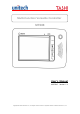
Multi-Function Versatile Controller MT688 User’s Manual 400790G Version 1.1 Copyright 2010 Unitech Electronics Co., Ltd. All rights reserved. Unitech is a registered trademark of Unitech Electronics Co., Ltd.
Copyright 2009 Unitech Electronics Co., Ltd. All rights reserved. Unitech is a registered trademark of Unitech Electronics Co., Ltd.
Preface About This Manual This manual explains how to install, operate and maintain the MT688 Multi-Function Versatile Controller. No part of this publication may be reproduced or used in any form, or by any electrical or mechanical means, without permission in writing from the manufacturer, which includes photocopying, recording, or information storage and retrieval systems. The material in this manual is subject to change without notice. © Copyright 2010 unitech Electronics Co., Ltd. All rights reserved.
¾ Increase the separation between the equipment and receiver. ¾ Connect the equipment into an outlet on a circuit that is different from the receiver. ¾ Consult the dealer or an experienced radio/television technician for help. 1. This Transmitter must not cohabitate or operate in conjunction with any other antenna(s) or transmitter(s). 2. This equipment complies with FCC RF radiation exposure limits set forth for an uncontrolled environment.
低功率射頻電機須忍受合法通信或工業、科學及醫療用電波輻射性電機設備之干 擾。 Warranty The following items are covered under Unitech Limited Warranty: z MT688 Multi-Function Versatile Controller – 1-year limited warranty. z Cables – three-month limited warranty. iii Copyright 2010 Unitech Electronics Co., Ltd. All rights reserved. Unitech is a registered trademark of Unitech Electronics Co., Ltd.
Table of Contents Preface About This Manual ............................................................................ i Regulatory Compliance Statements........................................................... i Warranty .................................................................................................. iii Chapter 1 Getting Started..............................................................................1 Introducing the MT688 ....................................................
Chapter 3 Data Communication .................................................................. 11 Establishing the USB Connection ...........................................................10 Establishing the MT688/PC Connection .................................................10 Using Mircosoft ActiveSync..................................................................... 11 Installing Microsoft ActiveSync......................................................... 11 Connecting the MT688 to the Computer.
Chapter 1 Getting Started Introducing the MT688 The MT688 is a versatile fixed-mount TASHI (Time & Attendance, Access Control, Surveillance, Home Automation and Intercom) Controller. This multi-functional device offers a built-in 2.0-Megapixel CMOS digital camera, RFID reader, microphone and audio speaker. It runs on a Windows CE 5.0 operating system which provides a variety of applications that benefit numerous industries.
Setting up the MT688 Connecting Power Connect power to the MT688 through the following instruction: Plug the Power Adapter Cable into the MT688’s DC input jack and then connect the other end of the Power Adapter into an electrical outlet. Powering On the MT688 The MT688 automatically powers on when the Power Adapter plugs into an external power source. The MT688 welcome screen appears, followed by the Windows CE screen. Using the MT688 for the First Time Using the Touch-screen 1.
2. 3. Double tap to open programs. Use the Windows CE Keyboard to type letters or numbers into a data field or on a form. Calibrating the Screen The calibration screen automatically appears when the MT688 is powered ON for the first time or when the system is reset. Tap a sequence of target marks across the screen. Tap gently, but firmly by touching the screen. The Date/Time properties screen will appear after the screen calibration has been confirmed.
Chapter 2 Using the Hardware Using the Function Buttons The MT688 contains six function Buttons. Function Buttons Function Key Descriptions F1 Function button F2 Function button (F3) Function button for calling the security guard (F4) Function button for door opening (F5) Function button enabling communication with administrator (F6) Function button for calling 4 Copyright 2010 Unitech Electronics Co., Ltd. All rights reserved. Unitech is a registered trademark of Unitech Electronics Co.
Using the Windows CE 6.0 Keyboard The Windows CE Software provides a touch-screen keyboard for alphanumeric input. The Windows-based keyboard replicates the layout of a standard PC keyboard. Open the Windows CE keyboard by tapping Æ LargeKB. Keyboard Icon Entering Characters Entering alphabetic and numeric characters on the MT688 is the same as character input on a standard PC keyboard. Tap the onscreen button corresponding to the desired character.
Using the RFID Reader (Optional) If your MT688 is provided with RFID reader, you will see the RFID reader logo on the front panel of MT688. The MT688 features a standard RFID reader, which is compatible with 13.56MHz MiFare cards. Testing RFID Card Verification The MT688 has built-in demo programs that allow RFID card verifications. 1. Double-tap the My Device icon on the Windows CE desktop. 2. Double-tap Windows. 3. Double-tap PDA_10 to open the demo program. 4. Set the COM Port: field at 2.
5. Choose a card type to activate the demo test program. 6. Tap Auto and bring the RFID card close to the sensor. The code will display on the field below. 7. Tap Stop to end the reading. Using the Camera The MT688 has a built-in 2.0-Megapixel camera that provides the following: z Capture still images. z Serve as video recorder. z Function as an audio/video intercom. z Incorporates facial recognition through third party software.
2. Double-tap Windows. 3. Double-tap CameraDemo to open the demo program. 4. Tap Preview → Start. A continuous image is displayed for capturing an image/audio/video. 5. 6. Tap Capture to photograph an image. To view the image, tap Preview → Stop. And, tap Playback → Show 7. 8. Image. Double-tap the image file name from the My Device folder. To exit the image, tap Playback → End Show Image. Exit the CameraDemo window by tapping X, or Preview → Exit.
2. Double-tap Windows. 3. Double-tap wavtest to open the demo program. 4. Do one of the following: -- Tap Rec to record the voice. -- Tap Stop to finish recording. -- Tap Play to listen to the recording. 9 Copyright 2010 Unitech Electronics Co., Ltd. All rights reserved. Unitech is a registered trademark of Unitech Electronics Co., Ltd.
Chapter 3 Data Communication The MT688 can link to a host computer for data communication via USB, RS232/485 or Ethernet cables. Establishing the USB Connection Connect a USB cable to the MT688’s USB host port, and connect the other end to a USB peripheral, such as a: Keyboard, mouse, memory card or HID compliant device.
connect the other end to the MT688’s RS232/485 Port. NOTE: Turn the RS232/485 Switch to the left (RS232) position. Ethernet Cable Plug an Ethernet cable into the PC’s RJ-45 ethernet port, and connect the other end of the cable into the MT688’s Ethernet Port. NOTE: In order for the Power-over-Ethernet module to support power over the RJ-45 Ether-net cable, the client side must have a POE Hub.
Connecting the MT688 to the Computer 1. 2. Power on the MT688. Connect a USB cable to the MT688’s USB host port, and connect the other end to a computer. 3. Microsoft ActiveSync starts automatically configuring the communication port to work with the MT688. The New Partnership setup wizard automatically starts. NOTE: Click Start → Programs → Microsoft ActiveSync if ActiveSync doesn’t automatically start.
6. Check Allow connection with desktop computer when device is attached. Tap OK. Establishing a Wi-Fi Connection The MT688 supports wireless communication with a built-in Wi-Fi card for 802.11b/g WLAN. It is possible to use the WiFi Utility to set up or modify the Wi-Fi settings through the following steps: NOTE: Wi-Fi access requires a separate service contract through a wireless service provider. Contact a wireless service provider for more information. Unitech terminals come with built-in RF facility.
3. Enter a Network Name (SSID) and a Network Key. For the detailed instruction on wireless network encryption setting, please visit Microsoft website. Then, tap OK. 4. The network icon appears on the taskbar when the RF is connected. Set Up an IP Address The MT688 automatically detects WLAN module during the first installation. Set the IP address through one of the following methods: z Obtaining an IP Address via Dynamic Host Configuration Protocol (DHCP) Server. z Specifying an IP Address.
1. Tap Start → Settings → Network and Dial-up Connections. NOTE: Tap Start → Settings → Control Panel → double-tap Network and Dial-up Connections. 2. Double-tap DM9000. 3. Tap the radio button next to Obtain an IP address via DHCP and then tap OK. Specifying an IP Address If no DHCP server is available, assign an IP address to each MT688 through the following: 1. Tap Start → Settings → Network and Dial-up Connections.
2. Double-tap DM9000. 3. Tap the radio button next to Specify an IP address. Input the proper IP address, Subnet Mask and Default Gateway. 4. In the Name Servers tab, input the proper Primary DNS:, Secondary DNS:, Primary WINS: and Secondary WINS:. Tap OK. NOTE: To avoid conflict with the Local Area Network environment, consult an MIS department for the correct Transmission Control Protocol / Internet Protocol setting. 16 Copyright 2010 Unitech Electronics Co., Ltd. All rights reserved.
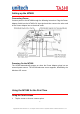
When using a PoE-enabled switch The MT688 is PoE-compliant, which allows it to be powered via a single Ethernet cable. If your switch/router supports PoE, refer to the following illustration to connect the MT688 to a PoE-enabled switch/router. 17 Copyright 2010 Unitech Electronics Co., Ltd. All rights reserved. Unitech is a registered trademark of Unitech Electronics Co., Ltd.
Chapter 4 Power and Hardware The MT688 must work with external power. In this case, connect the MT688 to the AC outlet with the power adapter. Adjusting the Backlight Adjust the backlight screen settings through the following steps: NOTE: The MT688 screen contrast has been preset by Unitech for optimum performance. 1. Tap Start → Settings → Control Panel → double-tap Backlight to adjust the screen brightness. 2.
Performing a Hardware Reset Perform a reset if the MT688 is frozen (i.e., the device no longer responds to pressing buttons on/or the touch-screen). Performing a Warm Boot A Warm Boot is used to reset or reboot the device without losing data stored in RAM memory. Perform a Warm Boot in any of the following situations: z The MT688 fails to respond. z After installing software applications. z After making changes to certain system settings (i.e. SD card). CAUTION! A Warm Start will erase all unsaved data.
Perform a Cold Boot by using the BootMode utility in the operating system, or by pressing the function Buttons on the MT688’s front panel. Perform a cold boot in the following situations: Reset the operating system. Restore the MT688 back to factory settings. Reset the MT688 after a boot loader, keyboard and kernel upgrade. CAUTION! A cold boot will erase all data and installed applications in RAM memory. Method 1: From Windows CE 1. Tap My Device → Windows → Boot. 2. Tap Warm Boot.
Using the Terminal Block The MT688 provides two 12-position terminal blocks for input/output signals. Insert the wire’s stripped end into the desired terminal block position. Tighten the lock screw to secure the wire.
Relay Output RL1-CTRL → High R1 (C & NO Linked) RL1-CTRL → Low R1 (C & NC Linked) RL2-CTRL → High R2 (C & NO Linked) RL2-CTRL → Low R2 (C & NC Linked) RL3-CTRL → High R3 (C & NO Linked) RL3-CTRL → Low R3 (C & NC Linked) RL4-CTRL → High R4 (C & NO Linked) RL4-CTRL → Low R4 (C & NC Linked) Digit Input D1+ and D1- are the positive and negative nodes of the external signal inputs.
23 Copyright 2010 Unitech Electronics Co., Ltd. All rights reserved. Unitech is a registered trademark of Unitech Electronics Co., Ltd.
Appendix A System Specification CPU Processor/Memory Memory Samsung 6410, 667Mhz Processor SDRAM: 128 MB Flash ROM: 128 MB OS Microsoft Windows CE 6.0 Professional Plus Button Six function buttons Display 8” SVGA (800 x 600) Pixels Backlight Touch-screen, TFT-LCD One RJ45 with POE (DC12V/1A, IEEE802.
Storage temperature -4℉~140℉(-20℃~60℃) Relative Humidity 5% – 95% RH non-condensing Certification CE, FCC, NCC, and RoHS compliant Programming Video Streaming RFID Reader (Optional) MiFare, 13.56MHz (ISO14443A/B & 15693, or ISO14443A only) 25 Copyright 2010 Unitech Electronics Co., Ltd. All rights reserved. Unitech is a registered trademark of Unitech Electronics Co., Ltd.
Appendix B Worldwide Support At unitech, we have a professional support team to answer your questions or any related technical issues. If the equipment problem occurs, you may contact our regional services representatives to get the quick response. We have six regional services center, and choose your region to get our quick sup-port and their contact information can be found in our websites provided as below. Region Web Site Global Operation Center http://www.ute.com Unitech Taiwan http://tw.ute.