
Instruction Manual

WASH SELECT II
Document Number: WS21058 79
Document Title: WSII Operations Manual ver 6.10
Appendix B. Circuit Board Connections
The following are pin out descriptions of the various connectors on the Wash Select II
components:
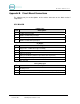
CPU BOARD
J1 Main Power
Pin Description
1 +5VDC main power input
2 GND for +5VDC main power input
3 +12VDC main power input
4 GND for +12VDC main power input
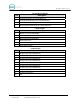
J21 Hopper
Pin Description
1 Hopper Run – 12VDC when hopper is running
2 Hopper Run Ground
3 Coins present Feed
4 Coins present Return (short this to pin 3 when coins are present)
5 Coin Drop (short this to pin 2 when coin drops)
6 Not connected
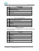
J20 Proximity Input
Pin Description
1 Proximity Feed +
2 Proximity Return (A short from this pin to pin 1 will activate proximity input)
3 N/C