
Installation Manual User Manual
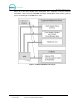
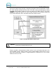
Table Of Contents
- 1 Site Planning
- 2 Tools Required for Installation
- 3 Mechanical Installation
- 4 Electrical Installation
- 5 Startup / Programming

WASH SELECT II
Document Number: WS21001 iii
Document Title: Wash Select II POS Installation Manual
Index of Figures
Figure 1. Conduits with Modem Line Layout....................................................................................2
Figure 2. Conduits with Ethernet Cable Layout ............................................................................... 3
Figure 3. Wash Select II Base Placement ....................................................................................... 5
Figure 4. Wash Select II Installation ..............................................................................................10
Figure 5. Straight Base .................................................................................................................. 11
Figure 6. Angled Base.................................................................................................................... 11
Figure 7. Setting Anchor Bolts ....................................................................................................... 12
Figure 8. Modem Wiring.................................................................................................................15
Figure 9. IPTran and DataTran Connections................................................................................. 16
Figure 10. Ethernet Cable Wiring Inside the Wash Select II.......................................................... 17
Figure 11. AC Connector ............................................................................................................... 20
Figure 12. Inside the AC Connector............................................................................................... 21
Figure 13. Thread Power Cord Through Line Insulator .................................................................21
Figure 14. Line - Neutral - Ground Connections............................................................................ 22
Figure 15. Intercom Adaptor Board................................................................................................ 23
Figure 16. Standard Wash Select II Keypad..................................................................................28
Figure 17. Wash out of Service Sequence .................................................................................... 30
Figure 18. Alternate Keypad Functions.......................................................................................... 38
Figure 19. Outside/Inside of IDX Coin Acceptor............................................................................49
Figure 20. Sample Site Layout....................................................................................................... 54
Figure 21. Gate Position ................................................................................................................ 56
Figure 22. Gate Reset Loop Dimensions.......................................................................................56
Figure 23. Gate Base Bolt Positioning........................................................................................... 57
Figure 24. Gate Wiring...................................................................................................................58
Index of Tables
Table 1. Wash Relays.................................................................................................................... 18
Table 2. Wash-In-Use Signal .........................................................................................................18
Table 3. Wash-fault SIGNAL..........................................................................................................19
Table 4. POS4000 Connection ...................................................................................................... 19
Table 5. J1 of Unitec Wash Card interface board.......................................................................... 24
Table 6. J 2 of Unitec Wash Card interface board......................................................................... 25
Table 7. Washcard input assignments...........................................................................................25
Table 8. J1 of Unitec Wash Card interface board.......................................................................... 25
Table 9. J 2 of Unitec Wash Card interface board......................................................................... 25
Table 10. 24 VAC Source Connection...........................................................................................26
Table 11. J1 of Unitec Wash Card Interface Board ....................................................................... 26
Table 12. J2 of Unitec Wash Card Interface Board ....................................................................... 27
Table 13. 24 VAC Connection .......................................................................................................27
Table 14. POS 4000 Cable Connections....................................................................................... 32
Table 15. Multi-Unit Fleet Cable Connections ...............................................................................33
Table 16. Remote Wash Select II Bay Addresses......................................................................... 34
Table 17. Pager Error Codes.........................................................................................................44
Table 18. Wash Select II Token Values.........................................................................................49
Table 19. Canadian IDX Program Configuration ...........................................................................50