
Installation Manual User Manual
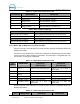
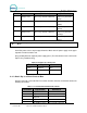
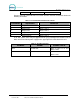
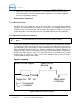
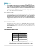
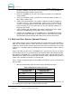
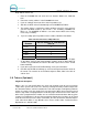
Table Of Contents
- 1 Site Planning
- 2 Tools Required for Installation
- 3 Mechanical Installation
- 4 Electrical Installation
- 5 Startup / Programming

WASH SELECT II
Document Number: WS21001 26
Document Title: Wash Select II POS Installation Manual
Number
(Old Version) (New Version)
1 Output 1 N.O. Express key JP5a Pin 4 (Button 4) Express key JP5a Pin 4
(Gray)
2 Output 2 N.O. Express key JP5a Pin 3 (Button 3) Express key JP5a Pin 3
(White)
3 Output 3 N.O. Express key JP5a Pin 2 (Button 2) Express key JP5a Pin 2
(Green)
4 Output 4 N.O Express key JP5a Pin 1 (Button 1) Express key JP5a Pin 1
(Orange)
5 Output Common Express key JP5a Pin 5 (Common) Express key JP5a Pin 5
(Black)
Note:
Express key should be configured for a 1 second output pulse
A 24 VAC power source may be tapped from the Wash Select II power supply on the upper
right of the inside back of the unit.
Grey proximity Block on top back power supply panel. (The chart below is for the old version
Express Key control box only)
Table 10. 24 VAC Source Connection
Terminal Signal Connect to
Pin 2 24AC hot Grey
Pin 10 N24AC neutral White
4.8.3 Hook Up to eWash Control Box
Remove connector J1 from the Ext Fleet card on the lower left of the I/O board and make the
following connections.
Table 11. J1 of Unitec Wash Card Interface Board
Pin Number Signal Name Connect to
1 Input 1 A eWash J5 Pin 6
2 Input 1 B Pin 5 of J1 (this connector)
3 Input 2 A
4 Input 2 B
5 10-16VDC+ Isolated Pin 2 of J1 (this connector)