
Installation Manual User Manual
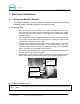
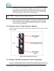
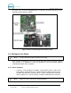
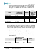
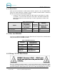
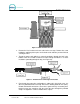
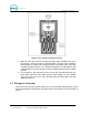
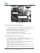
Table Of Contents
- 1 Site Planning
- 2 Tools Required for Installation
- 3 Mechanical Installation
- 4 Electrical Installation
- 5 Startup / Programming

WASH SELECT II
Document Number: WS21001 23
Intercom cable
2-wire connection: pin-1 =
audio/call feed. Pin-2 =
audio/call ground
Figure 15. Intercom Adaptor Board
4.7.1 Connecting a 2-wire Intercom System
1. Locate the 2-pin connector on the “Intercom Adapter Board”. (See Figure above.)
2. Use a small flathead screwdriver to loosen the screws on the top of the 2 pin connector.
3. Locate the “Audio/Call Feed” wire of the intercom system.
4. Attach the “Audio/Call Feed” wire to pin 1 and tighten the screw to pin 1.
5. Locate the “Audio/Call Ground” wire of the intercom system.
6. Attach the “Audio/Call Ground” wire to pin 2 and then tighten the screw to pin 2.
4.7.2 Connecting a 3-wire Intercom System
1. Locate the 3-pin connector on the “Intercom Adapter Board”. (See Figure 4.)
2. Use a small flathead screwdriver to loosen the screws on the top of the 3 pin connector.
3. Locate the “Call Feed” wire of the intercom system.
4. Attach the “Call Feed” wire to pin 1 of the 3-pin connector and then tighten the screw.
5. Locate the “Audio Feed” wire of the intercom system.
6. Attach the “Audio Feed” wire to pin 2 of the 3-pin connector and then tighten the screw.
7. Locate the “Audio/Call Ground” wire of the intercom system.
8. Attach the “Audio/Call Ground” wire to pin 3 of the 3-pin connector and then tighten the
screw.
Document Title: Wash Select II POS Installation Manual